Method and apparatus for providing structural support for interconnect pad while allowing signal conductance

a technology of interconnect pads and structural support, which is applied in the direction of individual semiconductor device testing, semiconductor/solid-state device testing/measurement, instruments, etc., can solve the problems of reduced bond pad strength, increased stress on the bond pad structure, and low modulus

Active Publication Date: 2006-07-13
NXP USA INC
View PDF19 Cites 64 Cited by
  • Summary
  • Abstract
  • Description
  • Claims
  • Application Information

AI Technical Summary

Problems solved by technology

A smaller bond pad region results in increased stress to the bond pad structure when a physical wire bond connection is made to the integrated circuit.
While the development of advanced low permittivity (low-k) dielectric materials has had a positive impact on integrated circuit electrical performance, these low-k materials typically exhibit a low modulus which reduces the strength of the bond pad structure.
In particular, bond pad structures fabricated with copper interconnect metallization and low modulus (low-k) dielectrics are susceptible to mechanical damage during the wire bonding process.
Additional to the compressive forces that may cause mechanical and structural failures, a lifting force associated with the tensioning of the bonded wire during movement of the wirebonding capillary after mechanical bonding may also cause structural damage to a wire bond.
Such structural damage may be visually undetectable and not become apparent until subsequent testing or operation.
This via arrangement requires that majority portions of the underlying metal layers and the bonding pad are all electrically connected together and thus are not functionally independent of each other.
Therefore, under the wire bond pad, these majority portions of the underlying two metal layers may not be used for wiring or interconnects unrelated to the pad.

Method used


Image

  • Method and apparatus for providing structural support for interconnect pad while allowing signal conductance
  • Method and apparatus for providing structural support for interconnect pad while allowing signal conductance
  • Method and apparatus for providing structural support for interconnect pad while allowing signal conductance

Examples


Embodiment Construction

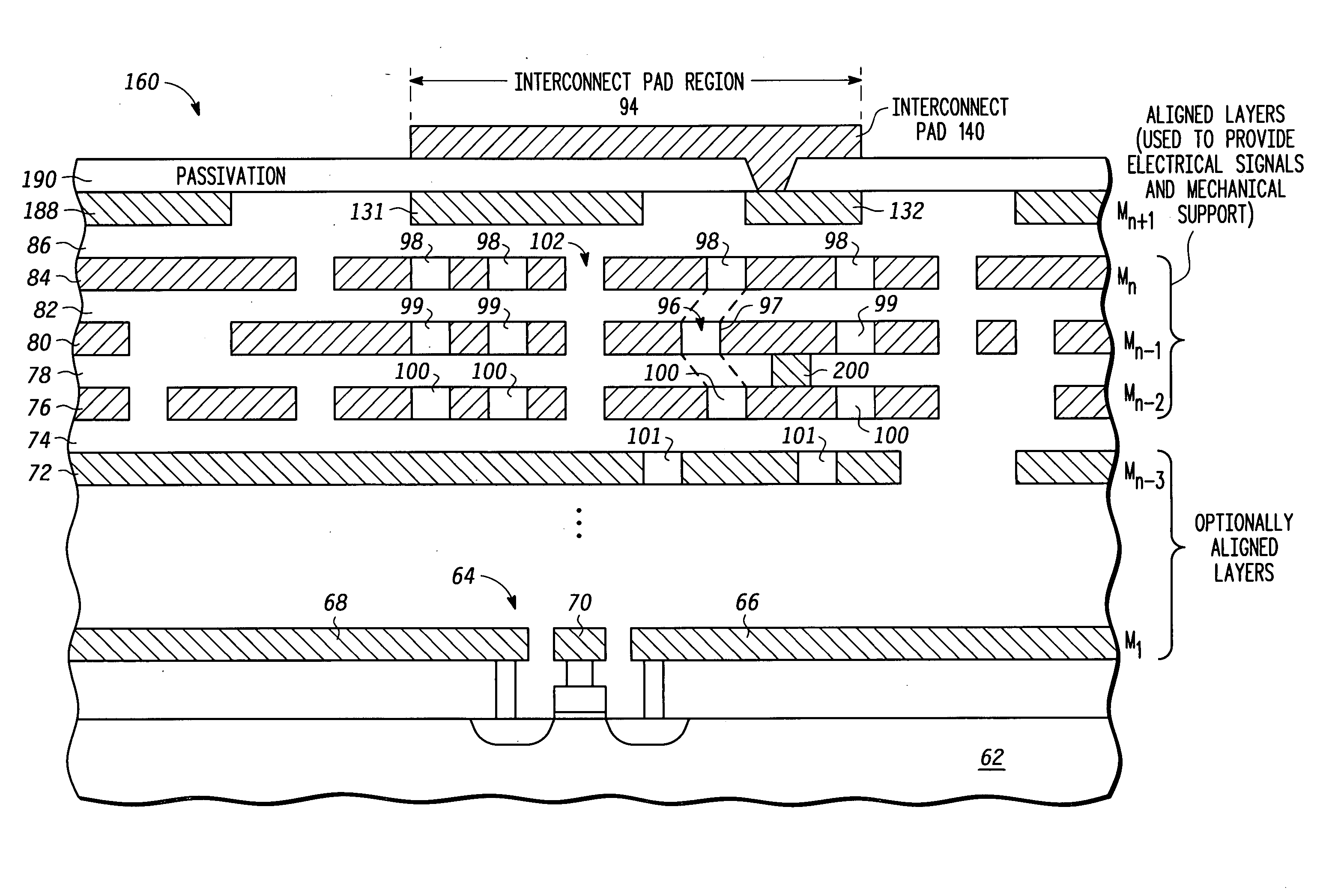
[0013] Generally there is herein provided a method and apparatus for providing structural support for interconnect pad locations in an integrated circuit (IC) by using novel layout techniques in the metallization and dielectric stack underlying the pad. As used herein, an interconnect pad, formed of metal, is placed at the surface of an integrated circuit where an electrical connection is made from the pad to one or more underlying metal layers. In a typical IC design, multiple metal layers separated by interlevel dielectrics are formed in a stack to provide the required interconnections between devices in the semiconductor substrate. Examples of an interconnect pad include, but are not limited to, a wire bond pad, a probe pad, a flip-chip bump pad, a test point or other packaging or test pad structures that may require underlying structural support. The interconnect pad region, located physically underneath the interconnect pad, defines the region in which the layout techniques pro...


PUM


Abstract

A method provides an interconnect structure having enhanced structural support when underlying functional metal layers are insulated with a low modulus dielectric. A first metal layer having a plurality of openings overlies the substrate. A first electrically insulating layer overlies the first metal layer. A second metal layer overlies the first electrically insulating layer, the second metal layer having a plurality of openings. An interconnect pad that defines an interconnect pad area overlies the second metal layer. At least a certain amount of the openings in the two metal layers are aligned to improve structural strength of the interconnect structure. The amount of alignment may differ depending upon the application and materials used. A bond wire connection or conductive bump may be used with the interconnect structure.

Description

FIELD OF THE INVENTION [0001] This disclosure relates to packaged semiconductors and more particularly to interconnect pads of integrated circuits for making electrical connection to underlying conductive layers. RELATED ART [0002] Wire bonding is a widely used method to connect a semiconductor die having electrical circuitry to a pin on a component package. As geometries in semiconductors continue to shrink in size due to improvements in the technology for making semiconductors, the sizes of wire bond pad regions have become smaller. A smaller bond pad region results in increased stress to the bond pad structure when a physical wire bond connection is made to the integrated circuit. The bond pad structure, which includes the metal bond pad itself and the underlying stack of metal interconnect and dielectric layers, mechanically supports the pad during wire bonding. While the development of advanced low permittivity (low-k) dielectric materials has had a positive impact on integrate...

Claims


Application Information

Patent Timeline
Patent Type & Authority Applications(United States)
IPC IPC(8): H01L21/4763
CPCH01L23/522H01L23/53214H01L23/53228H01L24/03H01L24/05H01L2224/05624H01L2924/01013H01L2924/01014H01L2924/01025H01L2924/01029H01L2924/01033H01L2924/01057H01L2924/01079H01L2924/014H01L2924/14H01L2924/19041H01L2924/19042H01L2924/19043H01L2924/00014H01L2924/01019H01L2224/023H01L2924/0001H01L21/4763
Inventor HESS, KEVIN J.DOWNEY, SUSAN H.MILLER, JAMES W.YONG, CHENG CHOI
Owner NXP USA INC
Why Eureka
Try Eureka