Substrate processing system and substrate processing program

a processing system and substrate technology, applied in the direction of program control, total factory control, instruments, etc., can solve the problems of unoptimized transfer procedure, adverse effects on the entire system, and low efficiency of transfer and process module operation rate, so as to improve the overall system's throughput and improve the effect of transfer efficiency

Active Publication Date: 2006-07-13
TOKYO ELECTRON LTD
View PDF3 Cites 38 Cited by
  • Summary
  • Abstract
  • Description
  • Claims
  • Application Information

AI Technical Summary

Benefits of technology

[0017] An object of the present invention, which has been completed by addressing the problems of the related art discussed above, is to provide a substrate processing system and a substrate processing program to be adopted in a cluster tool, with which wafers can be tran...

Problems solved by technology

Such a wafer a transfer procedure is less than ideal in that the transfer efficiency and the process module operation rates are not maximized.
In such a case, too, the transfer tactic in the entire system is adversely affected.
Such deterioration in the transfer tactic is bound to result in reduced ope...

Method used


Image

  • Substrate processing system and substrate processing program
  • Substrate processing system and substrate processing program
  • Substrate processing system and substrate processing program

Examples


first embodiment

Substrate Processing System Achieved in the First Embodiment

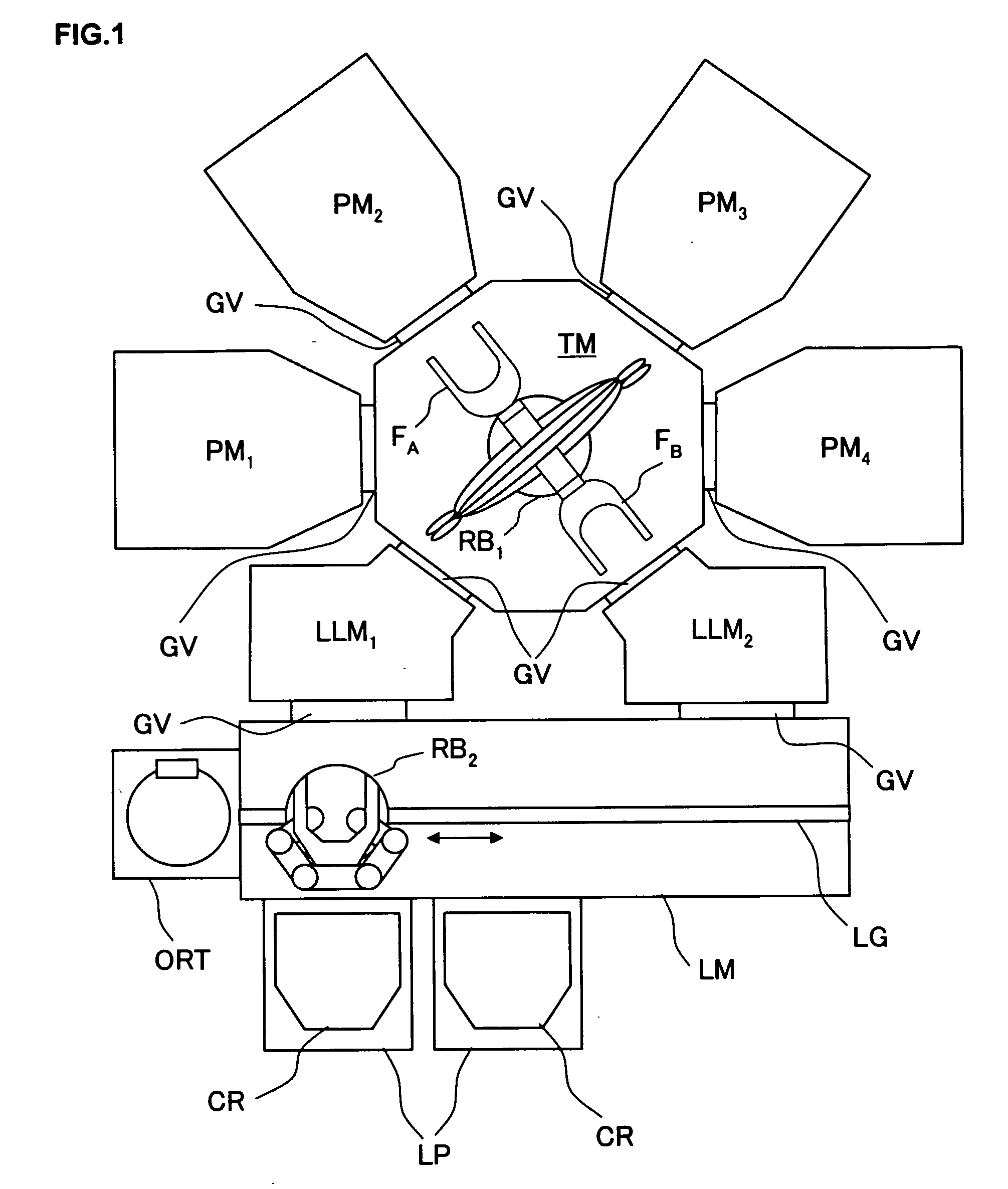
[0051] First, the substrate processing system achieved in the first embodiment of the present invention is explained in reference to drawings. FIG. 1 schematically shows the structure adopted in the substrate processing system achieved in the first embodiment. This substrate processing system includes a cluster tool (multichamber apparatus) achieved by connecting a plurality (e.g., four) of process modules (processing devices) PM1, PM2, PM3 and PM4 and two load-lock modules (load-lock chambers) LLM1 and LLM2 around a transfer module (vacuum transfer chamber) TM. The transfer module TM disposed at a substantial center of the cluster tool is connected with the individual modules PM1, PM2, PM3, PM4, LLM1 and LLM2 via gate valves GV each of which can be opened / closed freely.

[0052] The process modules each include a processing chamber (or a vacuum chamber) in which the pressure can be reduced to achieve a desired degree of vacu...

first implementation example

OF THE TRANSFER SEQUENCE

[0101] Next, the first implementation example of a transfer sequence that may be executed in conformance to the substrate processing program described above in the substrate processing system achieved in the embodiment is explained. FIG. 5 presents a specific example of the transfer sequence. Through the transfer sequence achieved in the first implementation example, a batch of wafers A (e.g., a predetermined number of wafers A01 through Anm) corresponding to a single cassette capacity, which have been loaded at a load port LP in the substrate processing system shown in FIG. 1, are sequentially transferred one wafer at the time, to the plurality of process modules PM1 and PM2 and the wafers A01 through Anm individually undergo a series of processing.

[0102] The shaded areas in FIG. 5 each indicate an active period of time (e.g., a period of time over which a wafer is being transferred during the wafer transfer processing, a period of time during which a wafer...

second implementation example

OF THE TRANSFER SEQUENCE

[0146] Next, the second implementation example of a transfer sequence that may be executed in conformance to the substrate processing program described above in the substrate processing system achieved in the embodiment is explained.

[0147] While only the process modules PM1 and PM2 in the cluster tool are engaged in operation and the other process modules PM3 and PM4 are not engaged in operation in the transfer sequence in the first implementation example explained above in reference to FIG. 5, all the process modules PM1, PM2, PM3 and PM4 in the cluster tool are simultaneously engaged in operation in the second implementation example.

[0148] The transfer sequence achieved in the second implementation example is shown in FIG. 7. The second implementation example is a specific example of a transfer sequence through which processing in a first pipeline processing system and processing in a second pipeline processing system are executed concurrently.

[0149] In ...


PUM


Abstract

In a substrate processing system according to the present invention, module cycle periods at a plurality of process modules PM1 through PM4 connected around a transfer module TM having installed therein a vacuum pressure-side transfer robot RB1, each representing the sum of a wafer stay time including the wafer processing time and an attendant busy time during which the wafer is transferred before and after the wafer stay time, are all set to a uniform length. The vacuum pressure-side transfer robot RB1 takes out a processed wafer Wi and carries a next wafer Wi+1 to be processed next by executing a pick and place operation for each of the process modules PM1 through PM4 during a single access to the process module.

Description

CROSS-REFERENCE TO RELATED APPLICATION [0001] This document claims priority to Japanese Patent Application No. 2005-002828, filed Jan. 7, 2005, the entire contents of which are hereby incorporated by reference. FIELD OF THE INVENTION [0002] The present invention relates to a substrate processing system and a substrate processing program for executing sequential processing on a batch of substrates transferred sequentially into a plurality of process modules, one substrate at a time. BACKGROUND OF THE INVENTION [0003] A substrate processing system used in this type of application in the related art may adopt a cluster tool (multi-chamber) structure with a plurality of process modules connected around a main transfer chamber (common transfer chamber) so as to integrate the flow of various processes to smooth the flow of the processes or to enable execution of more diverse processes. Typically, such a substrate processing system is adopted in conjunction with a semiconductor manufacturi...

Claims


Application Information

Patent Timeline
IPC IPC(8): G06F19/00H01L21/02H01L21/677
CPCG05B19/41865G05B2219/32077G05B2219/32306G05B2219/45032Y02P90/02G05B19/41815H01L21/67167H01L21/67276H01L21/67742H01L21/67745H01L21/68707G05B2219/45031
Inventor IKEDA, GAKU
Owner TOKYO ELECTRON LTD
Why Eureka
Try Eureka