Test program set obsolescence mitigation through software and automatic test equipment system processes

Active Publication Date: 2006-07-13
ADVANCED TESTING TECH
View PDF19 Cites 9 Cited by
  • Summary
  • Abstract
  • Description
  • Claims
  • Application Information

AI Technical Summary

Benefits of technology

[0023] An electronic test system which provides for obsolescence mitigation in accordance with the invention includes hardware and software components selectively coupled together. That is, the software can be embodied on hardware components, e.g., memory components, connected to other hardware components using conventional cabling and wireless arrangements. The components enable creation of a test program test (TPS) for the system and testing of units using the TPS, e.g., by coupling the unit under test (UUT) to one of the hardware components using conventional cabling or wireless arrangements. The software detects a change in the system caused by introduction of a new component into the system, in a manner known to those skilled in the art, and then enables creation of a new TPS and determines whether the new TPS complies with a set of governing rules for the system. The new TPS can be created by a user of the electronic test system or a

Problems solved by technology

Since the inception of automated test systems or automated test equipment, engineers have struggled with the dilemma of delivering a cost effective solution to provide optimum testing of electronic equipment.
Early versions were typically company proprietary and often, no standard existed to guide interoperability of different products.
This is beneficial from the interoperability standpoint, but alone will not likely provide a cost effective solution.
A particular problem of using commercial technology and standards is the tendency or possibility for a single entity, usually the most deep-pocketed entity, to influence the commercial world in their favor.
This typically causes the promise of cost savings, expected to be achieved using a commercial standard, to be eroded due to significant single entity influence.
The initiation of a commercial standard through professional organizations such as the IEEE can take far too long and consequently, a technology can be obsolete before a use standard is complete.
This often causes ineff

Method used


Image

  • Test program set obsolescence mitigation through software and automatic test equipment system processes
  • Test program set obsolescence mitigation through software and automatic test equipment system processes
  • Test program set obsolescence mitigation through software and automatic test equipment system processes

Examples


Embodiment Construction

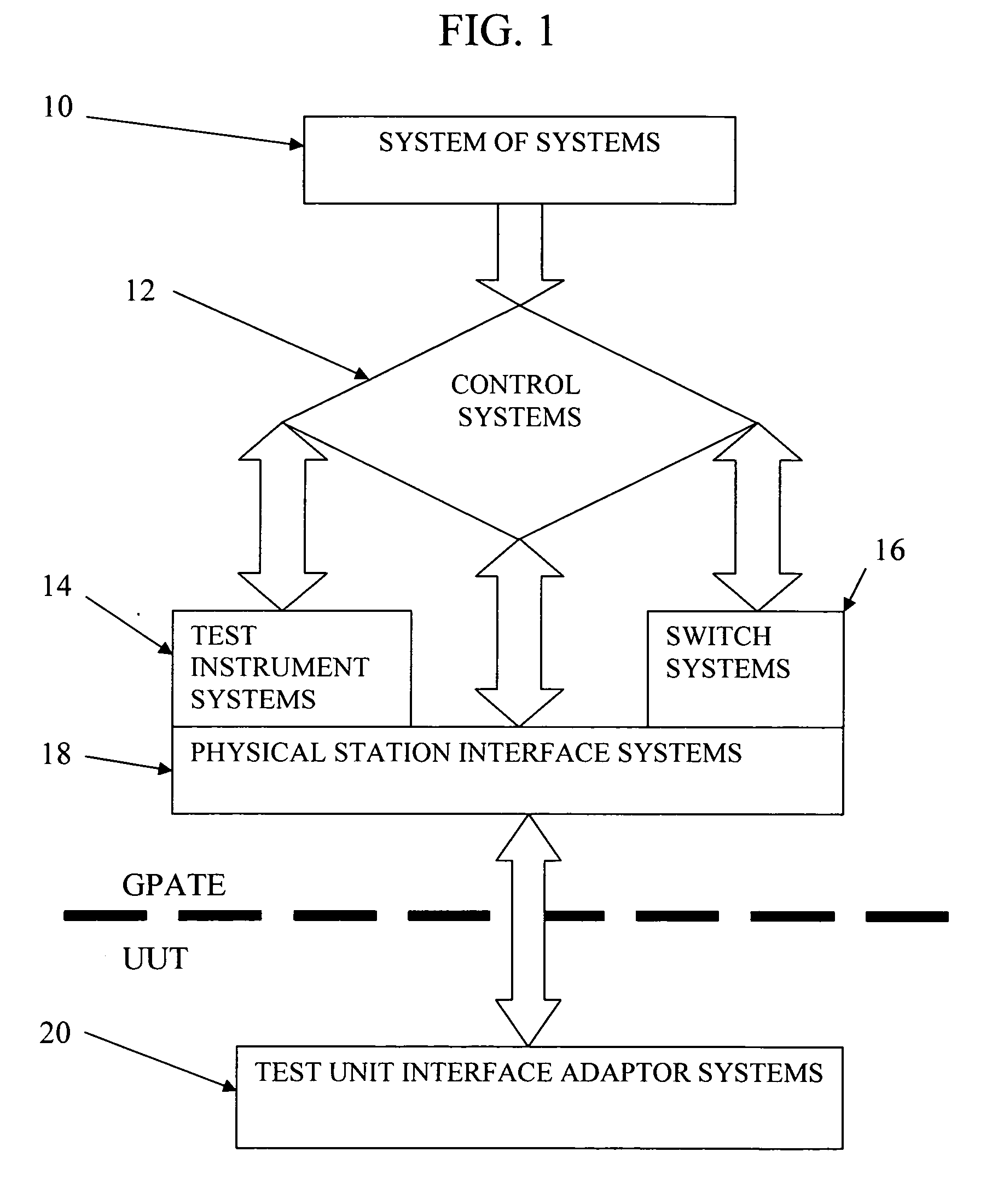
[0027] Referring to the accompanying drawings wherein like reference numerals refer to the same or similar elements, FIG. 1 illustrates the hierarchy of a system in accordance with the invention, i.e., a system of subsystems 10. The system of subsystems 10 includes one or more control systems 12 which controls test instrument systems 14, switch systems 16 and physical station interface systems 18. The physical station interface systems 18 are coupled to test unit interface adaptor systems 20. The system of subsystems 10 contains hardware and software components for which obsolescence mitigation is desired.

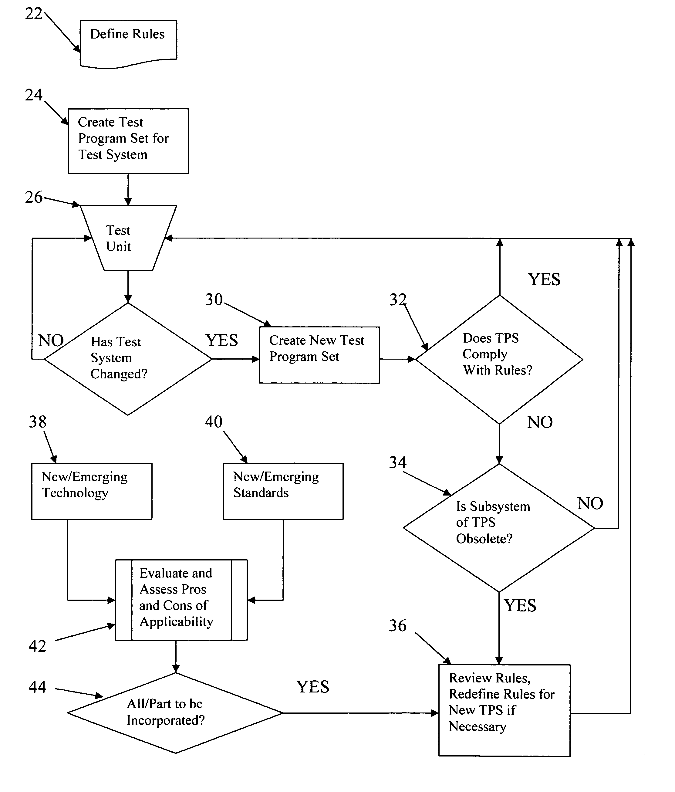
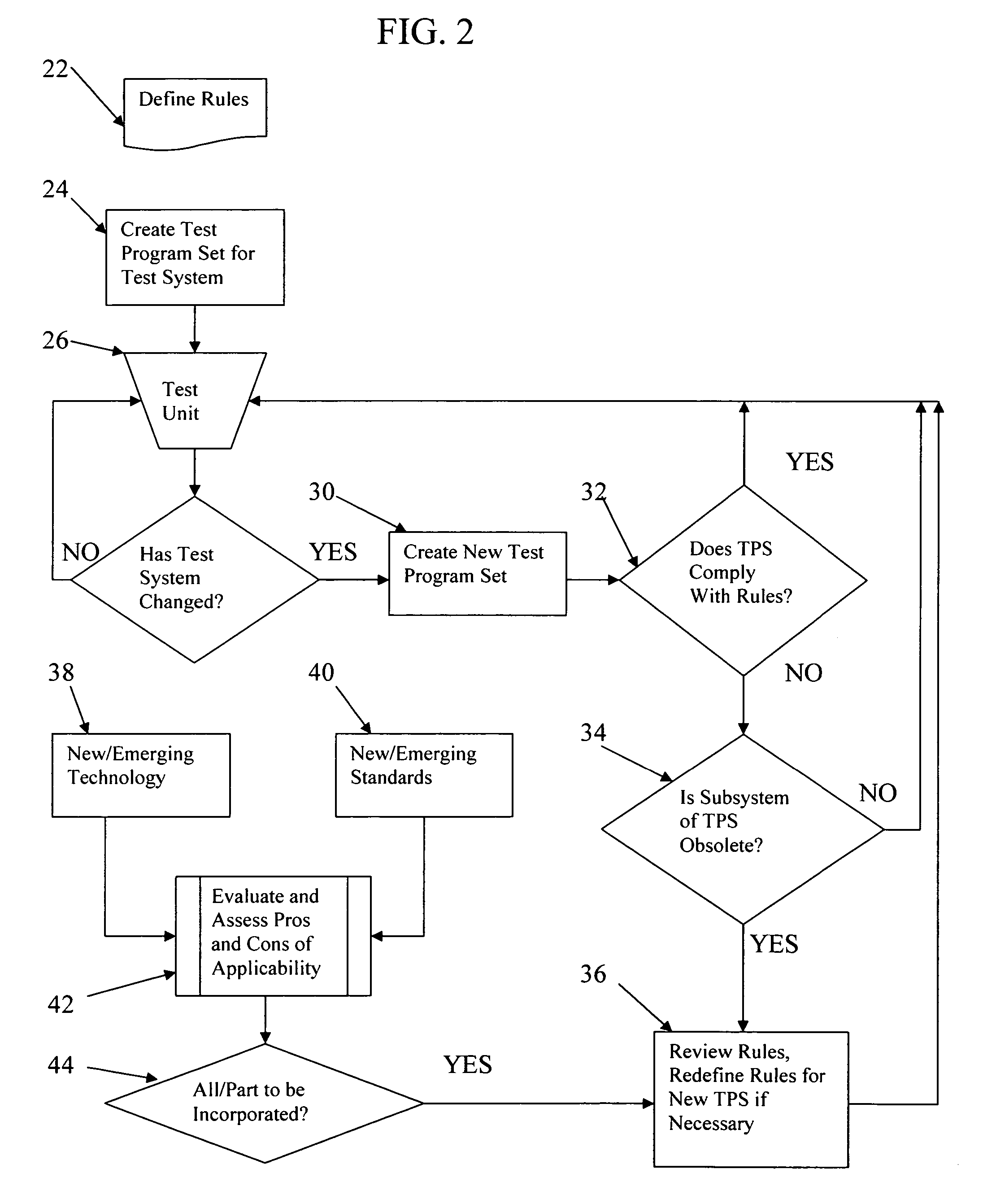
[0028]FIG. 2 shows a flow chart of one non-limiting method in accordance with the invention for designing and maintaining a system of subsystems, namely, an automated test system comprising hardware and software components and documentation. The method is effective on the system's hardware, software, documentation, development environments, support tools, test program development ...


PUM


Abstract

Electronic test system including hardware and software components and method of use of same which provide obsolescence mitigation. A set of governing rules for the system is defined and a test program test (TPS) is created to enable units to be tested. When a new component is introduced into the system, the change is detected and a new TPS is created. If the new TPS complies with the rules, testing using the new TPS is possible. If not, a determination is made as to whether any component of the TPS is obsolete and if not, the units can be tested using the new TPS without redefining the rules. When a component of the TPS is obsolete, the rules are reviewed to ascertain the effect of the removal of the component and optionally redefined to enable the new component to be used in combination with the remaining components.

Description

CROSS-REFERENCE TO RELATED APPLICATION [0001] This application claims priority under 35 U.S.C. §119(e) of U.S. provisional patent application Ser. No. 60 / 643,248 filed Jan. 12, 2005, which is incorporated by reference herein.FIELD OF THE INVENTION [0002] The present invention relates generally to methods and systems for obsolescence mitigation of electronic systems including hardware and software components and more particularly to methods and systems for dealing with obsolete hardware and software in automated test systems to enable transparent updating of the automated test systems and applications. [0003] The present invention also relates generally to methods and systems for performing production, functional and diagnostic tests using automated test systems and subsystems to enable subsequent repair to serviceable status of the systems and subsystems, or to certify functional readiness of the systems and subsystems for insertion thereof into a larger functional assembly. BACKGRO...

Claims


Application Information

Patent Timeline
IPC IPC(8): G06F9/44
CPCG01R31/2834G01R31/31908G06F11/3672
Inventor SPINNER, ROBERT
Owner ADVANCED TESTING TECH
Why Eureka
Try Eureka