
Clad window frame with improved sealing

a window frame and sealing technology, applied in the field of fenestration, can solve the problems of considerable skill and patience required during application, water leakage to the underlying wooden window frame elements, and particularly troublesome joints, and achieve the effects of reducing the criticality of traditional sealants

Inactive Publication Date: 2006-07-20
ANDERSEN CORPORATION
View PDF8 Cites 6 Cited by
  • Summary
  • Abstract
  • Description
  • Claims
  • Application Information

AI Technical Summary

Benefits of technology

[0006] Briefly described, the present invention, in one preferred embodiment thereof, comprises an improved and enhanced cladding system for clad windows that substantially eliminates leaks at the bottom corners of windows and also eliminates or at least reduces the criticality of traditional sealants applied in these locations. The invention includes a sill cladding that is shaped to define a barrier pan having upwardly extending end walls configured to project upwardly a short distance beneath the vertical jamb liners of the window. An upturned or upwardly extending interior edge wall extends along the inside edge of the barrier pan between the upwardly extending end walls. The barrier pan with its upwardly extending end and edge walls thus forms a sill cladding that captures any moisture that may leak through the joint between the sill cladding and jamb liners and prevents the moisture from penetrating through to underlying wooden elements of the window frame. While sealant still can, and likely should, be used at critical cladding joints, the criticality of this sealant and its application is greatly reduced because the consequences of leakage are virtually eliminated by the unique barrier pan of the present invention.
[0007] According to a preferred embodiment, the barrier pan is formed of thermoplastic polymeric material such as PVC by traditionally known fabrication methods such as injection molding or thermoforming. Other materials, such as aluminum, also can be used. Further, the barrier pan can be formed of multiple assembled components such as, for instance, a pan portion to provide the barrier function and a cover portion to provide suitable appearance and weatherability. During window unit assembly, the barrier pan cladding is installed covering the sill of a window with its end walls extending partially up the vertical side jambs. Jamb liners are then installed, with the bottoms of the jamb liners overlapping the end walls of the barrier pan. Other cladding components also may be attached to the frame. Assembly may include the application of a sealant at the junction of the jamb liners and barrier pan to reduce the likelihood of leakage; however, such a sealant may not be required at all because any leakage that occurs is captured by the upwardly extending end walls and inside edge wall of the barrier pan and directed outward to the edge of the sill, where it can drain away from the window in the usual way.
[0008] Thus, a window cladding system is now provided that virtually eliminates leakage at the bottom corners of the window where leakage has traditionally been a primary concern. At the same time, the cladding system is simple and efficient to install during window unit assembly, does not involve the elevated skill level required in the past for sealant application, and is not likely to develop leaks over time. These and other objects, features, and advantages of the window cladding system of this invention will become more apparent upon review of the detailed description set forth below, when taken in conjunction with the accompanying drawing figures, which are briefly described as follows.

Problems solved by technology

One such joint that historically has been particularly troublesome is the joint between the cladding that covers a window sill and the jamb liners that cover the inside faces of the window jambs.
These joints occur at the bottom corners of the window frame and, unless properly sealed, can result in water leakage to underlying wooden window frame elements.
While such sealants can produce adequate sealing, particularly in the short term, it has been found that considerable skill and patience may be required during application to avoid sealing defects, a limitation that may be incompatible with manufacturing requirements because of the likelihood of immediate or eventual leaks.
Even where sealing is applied precisely according to requirements, the sealed joints can, over time, develop leaks due to a number of factors including, for instance, thermal expansion and contraction of cladding components, movement and settlement, and physical damage.
However, leaks often can develop along these joints anyway, resulting in rotting and deterioration of the underlying wooden window frame elements.

Method used


Image

  • Clad window frame with improved sealing
  • Clad window frame with improved sealing
  • Clad window frame with improved sealing

Examples


Embodiment Construction

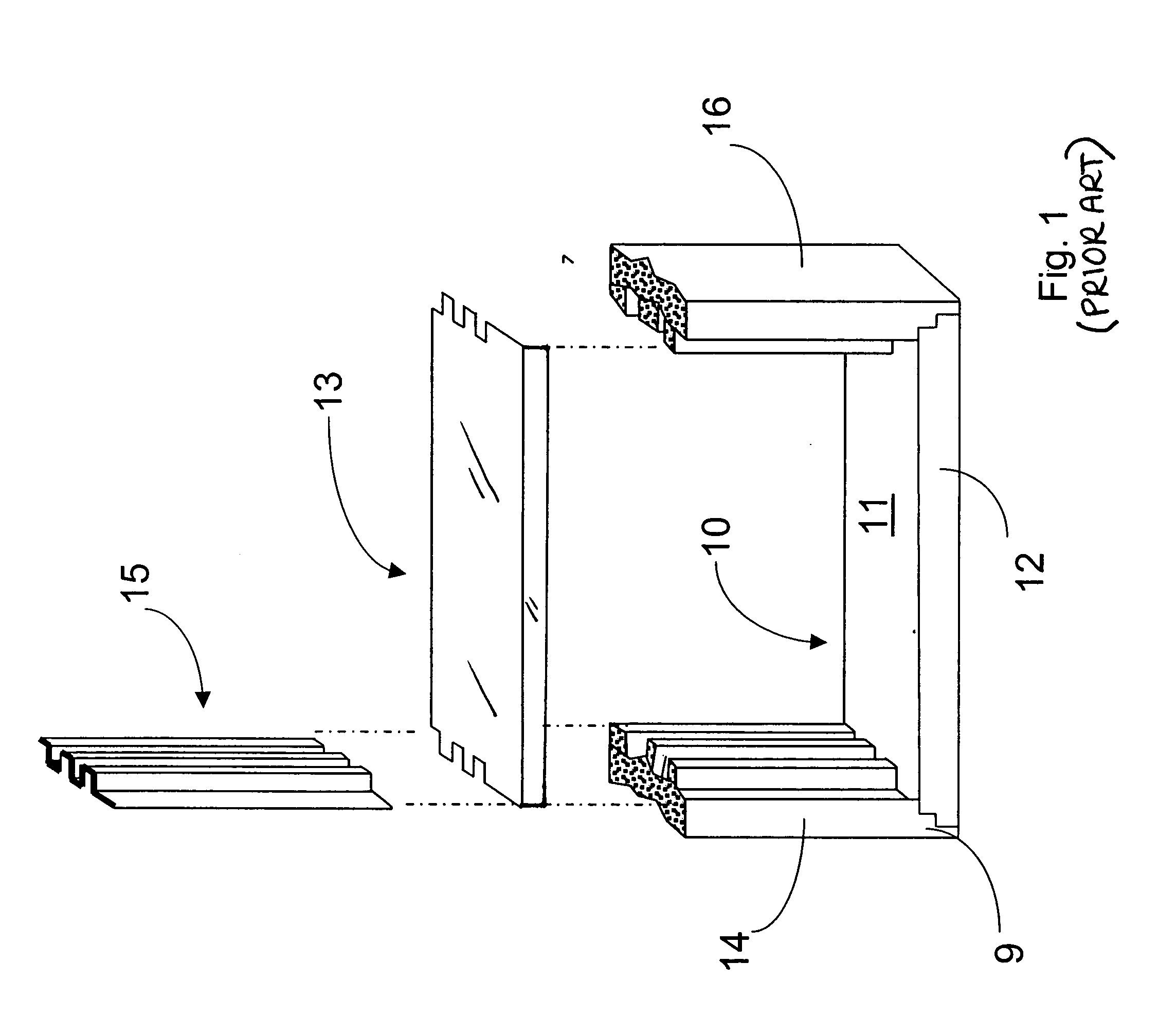
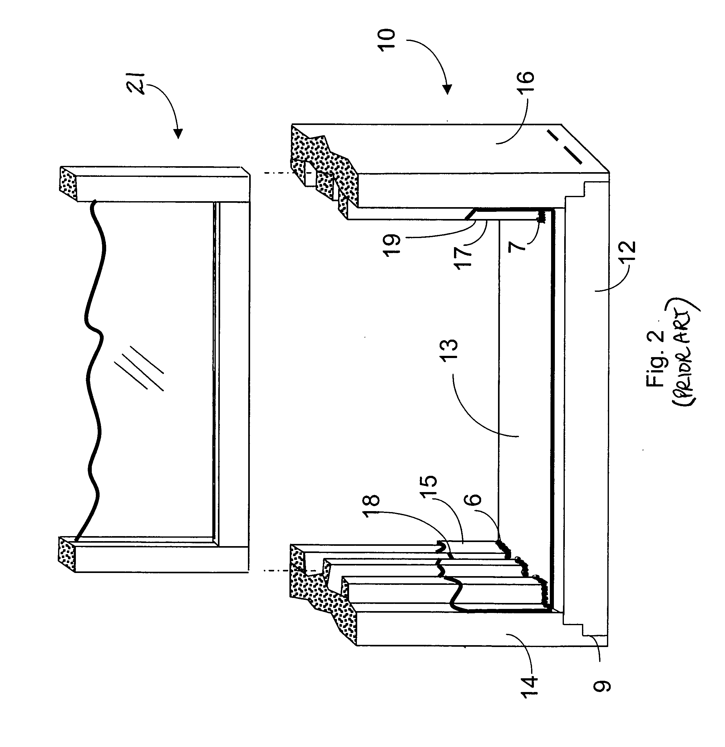
[0015] Referring now in more detail to the drawing figures, wherein like reference numerals indicate, where appropriate, like parts throughout the several views, FIGS. 1 and 2 illustrate, in simplified form, a prior art clad window unit, which is discussed in some detail above. FIGS. 3 through 6 illustrate embodiments of the present invention, which will now be discussed in more detail.

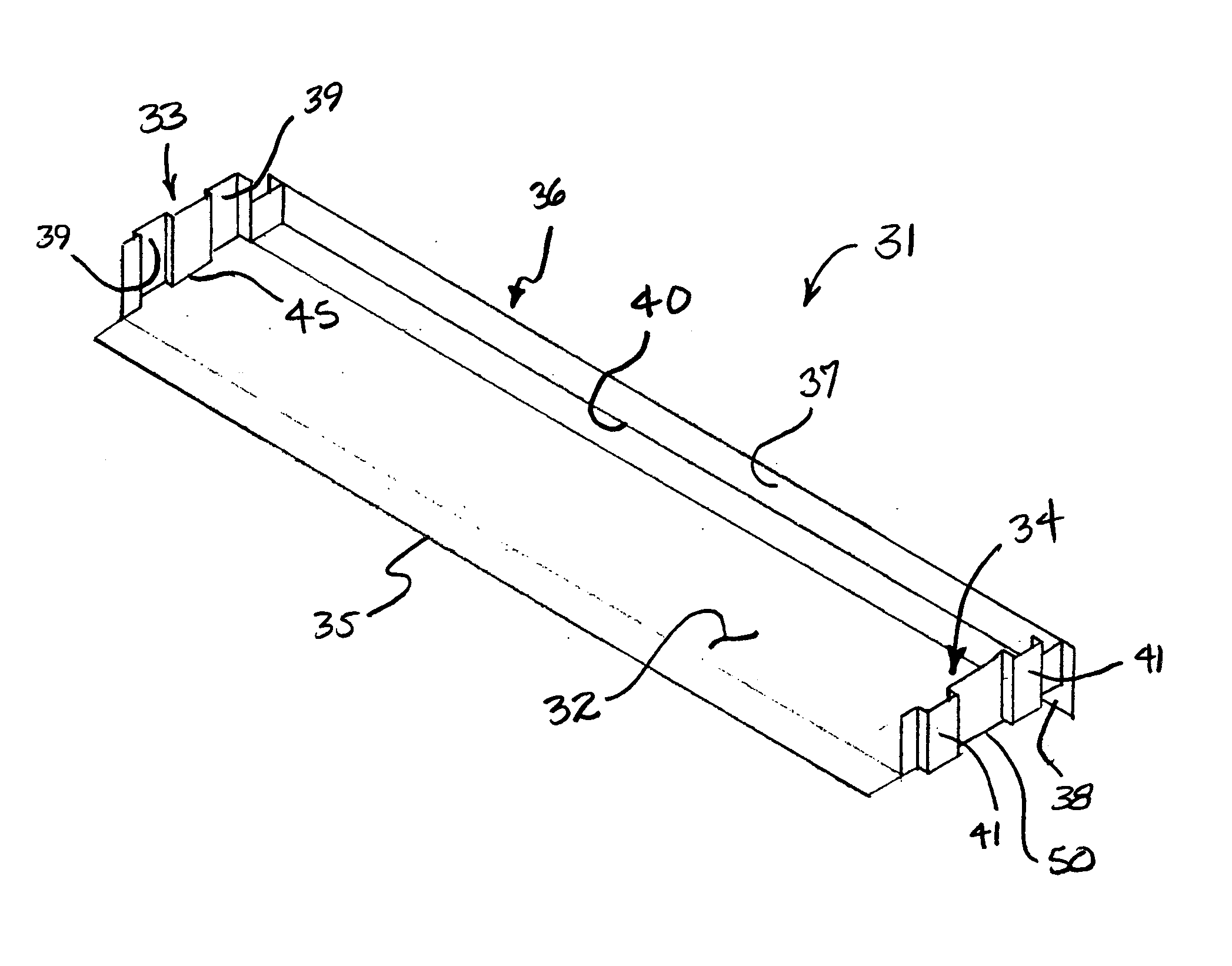
[0016]FIG. 3 shows an improved window sill cladding in the form of a barrier pan 31 that embodies principles of the present invention in one preferred form. The window barrier pan preferably is molded of a single unitary piece of relatively thin-walled water proof material such as, for instance, PVC plastic. The barrier pan 31 generally is shaped and configured to conform to the profile of the window sill it will cover. More specifically, the barrier pan 31 has a relatively flat floor 32 that is shaped to conform to the profile of the upper surface of a window sill. The floor 32 extends outwardly to ...


PUM


Abstract

A leak resistant clad window has a sill, spaced vertical jambs, and a header. A barrier pan is installed over and clads the sill of the window and includes upwardly extending end walls that extend partially up the vertical jambs. Jamb liners are installed on the inside faces of the jambs and the bottom portions of the jamb liners overlie the upwardly extending end walls of the barrier pan. An inside edge wall projects upwardly along an inside edge of the barrier pan and extends between the end walls. The barrier pan preferably is made of a unitary piece of molded plastic. Water that may seep into joints, particularly at the bottom corners of the window, are captured in the barrier pan and directed outwardly to be shed away from the window.

Description

TECHNICAL FIELD [0001] This Invention relates generally to fenestration and more particularly to prevention or reduction of leaks at the bottom corners of a clad window frame. BACKGROUND [0002] Fenestration units such as window frames often are waterproofed and protected from weathering by cladding them with formed sheets of material resistant to weathering and water penetration. Typical cladding materials include, for example, plastics, such as polyvinyl chloride (PVC), and aluminum. Cladding components may be produced by molding, extruding, bending, or otherwise forming the cladding material into pieces having shapes that conform to the profiles of at least the exterior portions of underlying window frame elements, such as jambs, sills, and headers, which often are made of wood. The formed cladding is then fitted and attached to the wooden elements of the frame to cover the wood and protect it from moisture and attendant rot and decay. Cladding components typically are held in pla...

Claims


Application Information

Patent Timeline
Patent Type & Authority Applications(United States)
IPC IPC(8): E06B3/00
CPCE06B1/702E06B1/705
Inventor WEISS, DAVID J.
Owner ANDERSEN CORPORATION
Features
  • Generate Ideas
  • Intellectual Property
  • Life Sciences
  • Materials
  • Tech Scout
  • Unparalleled Data Quality
  • Higher Quality Content
  • 60% Fewer Hallucinations
Learn More