Exhaust-gas return system for an internal-combustion machine and method of returning exhaust gas

a return system and exhaust gas technology, applied in the direction of exhaust gas recirculation, non-fuel substance addition to fuel, mechanical apparatus, etc., can solve the problems of bypassing the turbine and not being able to extract heat from the exhaust, and achieve the effect of improving the cold start behaviour

Inactive Publication Date: 2006-07-20
PIERBURG GMBH & CO KG NEUSS
View PDF4 Cites 15 Cited by
  • Summary
  • Abstract
  • Description
  • Claims
  • Application Information

AI Technical Summary

Benefits of technology

[0007] It is an object of the present invention to provide an exhaust gas retur...

Problems solved by technology

The turbine is thus bypassed and is not...

Method used


Image

  • Exhaust-gas return system for an internal-combustion machine and method of returning exhaust gas
  • Exhaust-gas return system for an internal-combustion machine and method of returning exhaust gas

Examples


Embodiment Construction

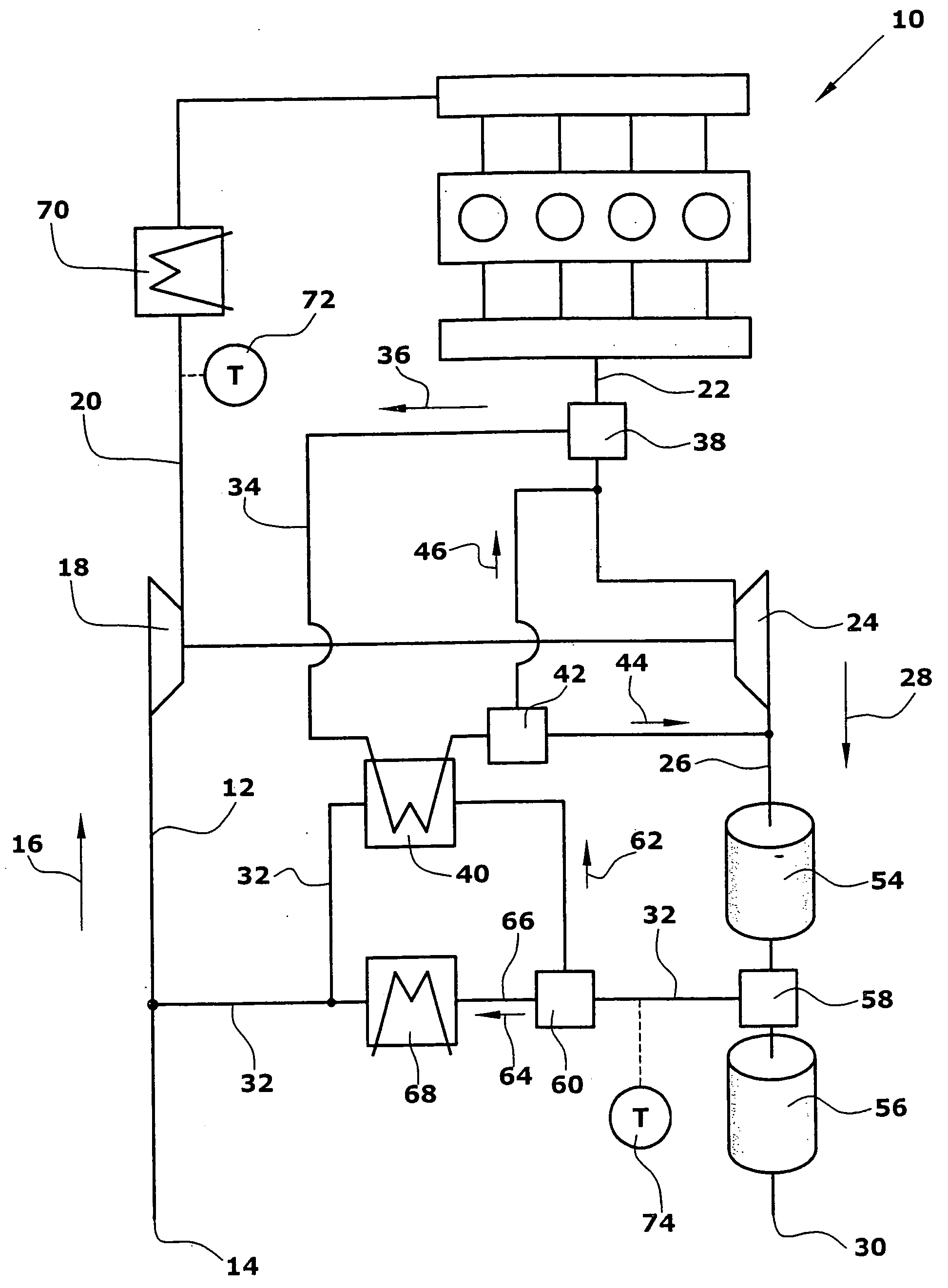
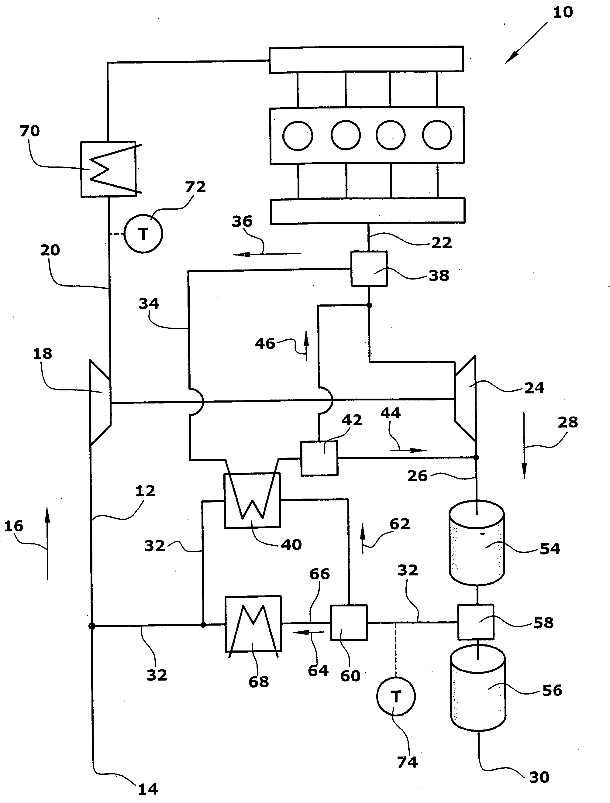
[0020] The exhaust gas return system according to the invention for an internal-combustion machine 10 comprises a low-pressure supply line 12 which feeds fresh air in the direction indicated by an arrow 16 from an inlet 14 to a compressor 18. From the compressor 18 a high-pressure supply line 20 extends to the internal-combustion machine 10. From the internal-combustion machine 10 a high-pressure exhaust gas line 22 extends to a turbine 24. From the turbine 24 a low-pressure exhaust gas line 26 extends in the direction indicated by an arrow 28 to an outlet 30. The low-pressure exhaust gas line 26 and the low-pressure supply line 12 have connected therewith a low-pressure return line 32.

[0021] The high-pressure exhaust gas line 22 has connected therewith a bypass line 34 which feeds at least part of the exhaust gas produced in the internal-combustion machine 10 in the direction indicated by an arrow 36. The volume flow fed in the direction indicated by an arrow 36 can be adjusted by...


PUM


Abstract

An exhaust gas return system for an internal-combustion machine which comprises a low-pressure supply line extending from an inlet to a compressor. From the compressor a high-pressure supply line extends to the internal-combustion machine. From the internal-combustion machine a high-pressure exhaust gas line extends to a turbine. From the turbine a low-pressure exhaust gas line extends to an outlet. The low-pressure exhaust gas line and the low-pressure supply line have connected therewith a low-pressure return line for returning exhaust gas. The high-pressure exhaust gas line has connected therewith a bypass line for utilizing the heat of the exhaust gas produced in the internal-combustion machine for heating the exhaust gas to be returned of the low-pressure return line before the exhaust gas is supplied to the turbine (24), if desired. Thus the cold start phase of the internal-combustion machine can be reduced.

Description

BACKGROUND OF THE INVENTION [0001] 1. Field of the Invention [0002] The present invention relates to an exhaust gas return system for an internal-combustion machine, in particular a diesel engine, for returning exhaust gas produced in the internal-combustion machine to fresh air to be supplied to the internal-combustion machine. Further, the invention relates to a method of returning exhaust gas, wherein the exhaust gas of the internal-combustion machine can be returned to the fresh air used for the internal-combustion machine. [0003] 2. Description of Related Art [0004] Conventional exhaust gas return systems comprise a piping system extending from an outlet of an internal-combustion machine to an inlet. For this purpose, the exhaust gas return system comprises a low-pressure supply line extending from an inlet to a compressor. A high-pressure supply line extends from the compressor to the internal-combustion machine for supplying fresh air aspirated at the inlet to the internal-co...

Claims


Application Information

Patent Timeline
IPC IPC(8): F02B33/44
CPCF01N3/035F01N5/02F02B29/0406F02B37/18F02M25/0709F02M25/0718F02M25/0719F02M25/0728F02M25/0738F02M25/074F02M25/0754Y02T10/121Y02T10/144Y02T10/16F01N13/009F02M26/06F02M26/15F02M26/16F02M26/25F02M26/33F02M26/35F02M26/47Y02T10/12
Inventor DISMON, HEINRICHKOESTER, ANDREAS
Owner PIERBURG GMBH & CO KG NEUSS
Why Eureka
Try Eureka