Exhaust-gas return system for an internal-combustion machine and method of returning exhaust gas

a return system and exhaust gas technology, applied in the direction of exhaust gas recirculation, non-fuel substance addition to fuel, mechanical apparatus, etc., can solve the problems of bypassing the turbine and not being able to extract heat from the exhaust, and achieve the effect of improving the cold start behaviour

Inactive Publication Date: 2008-03-18
PIERBURG GMBH & CO KG NEUSS
View PDF6 Cites 13 Cited by
  • Summary
  • Abstract
  • Description
  • Claims
  • Application Information

AI Technical Summary

Benefits of technology

[0007]It is an object of the present invention to provide an exhaust gas return system and a method of returning exhaust gas with an improved cold start behaviour.
[0011]By means of the bypass line it is possible, due to return of the exhaust gas, to use the heat of the hot exhaust gas for heating the exhaust gas to be returned and / or for heating the fresh air to be supplied, without the contaminants contained in the exhaust gas being returned to the internal-combustion machine. Further, a high-pressure return line, which may be necessary otherwise, can be omitted. Moreover, the heat of the exhaust gas is preferably used for heating the exhaust gas to be returned and only then for heating the turbine which, in particular together with the compressor, constitutes a turbo-charger. A delay in the heating of the exhaust gas to be returned caused by the heat capacity of the turbocharger is thus prevented. Further, higher temperatures are more rapidly reached in the low-pressure exhaust gas line such that any existing catalyst more rapidly operates in the optimal range. In particular when part of the exhaust gas is directed past the turbine, an exhaust gas treatment device which may be provided in the low-pressure exhaust gas line, e.g. a catalyst, is heated before heating the turbocharger, whereby the emission of harmful exhaust gases and substances, such as Nox, CO, SO2, is reduced. Since the rapid heating of the fresh air promotes as complete a combustion in the internal-combustion machine as possible, emission of harmful exhaust gases and substances is further reduced.
[0012]In a preferred embodiment, the bypass line and / or the high-pressure exhaust gas line comprise a bypass valve for adjusting the volume flow into the bypass line. This in particular allows, for example during the cold start phase and / or the idle phase of the combustion engine, a particularly high volume flow to be directed through the bypass line and to correspondingly reduce the volume flow with gradual increase in the temperature of the fresh air. This allows the bypass line to be closed during the warm-up phase or when suddenly a particularly high output of the combustion engine is required, such that as much energy as possible of the exhaust gas from the internal-combustion machine can be utilized in the compressor.

Problems solved by technology

The turbine is thus bypassed and is not allowed to extract heat from the exhaust gas.

Method used


Image

  • Exhaust-gas return system for an internal-combustion machine and method of returning exhaust gas
  • Exhaust-gas return system for an internal-combustion machine and method of returning exhaust gas

Examples


Embodiment Construction

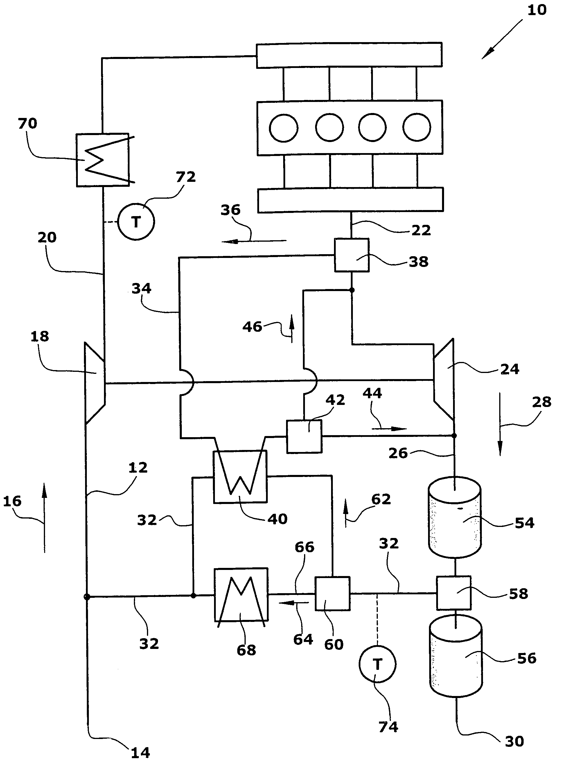
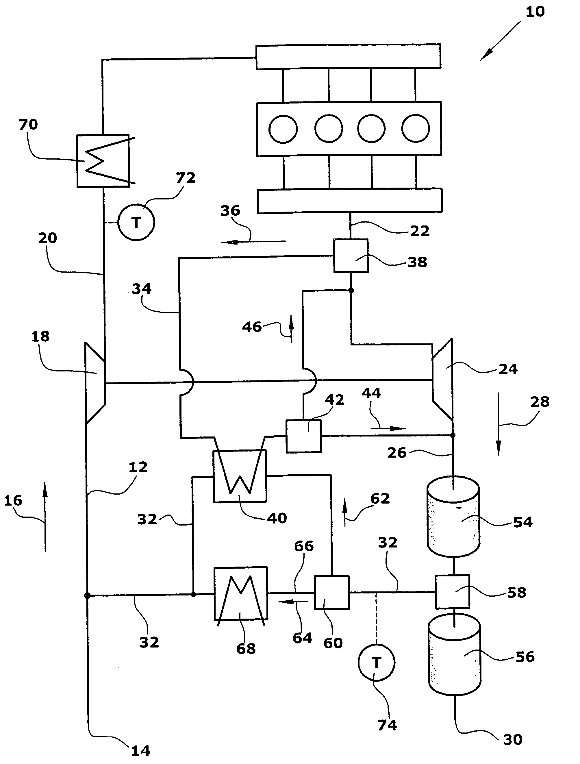
[0020]The exhaust gas return system according to the invention for an internal-combustion machine 10 comprises a low-pressure supply line 12 which feeds fresh air in the direction indicated by an arrow 16 from an inlet 14 to a compressor 18. From the compressor 18 a high-pressure supply line 20 extends to the internal-combustion machine 10. From the internal-combustion machine 10 a high-pressure exhaust gas line 22 extends to a turbine 24. From the turbine 24 a low-pressure exhaust gas line 26 extends in the direction indicated by an arrow 28 to an outlet 30. The low-pressure exhaust gas line 26 and the low-pressure supply line 12 have connected therewith a low-pressure return line 32.

[0021]The high-pressure exhaust gas line 22 has connected therewith a bypass line 34 which feeds at least part of the exhaust gas produced in the internal-combustion machine 10 in the direction indicated by an arrow 36. The volume flow fed in the direction indicated by an arrow 36 can be adjusted by me...


PUM


Abstract

An exhaust gas return system for an internal-combustion machine which comprises a low-pressure supply line extending from an inlet From the compressor. a high-pressure supply line extends to the internal-combustion machine. From the internal-combustion machine a high-pressure exhaust gas line extends to a turbine. From the turbine a low-pressure exhaust gas line extends to an outlet. The low-pressure exhaust gas line and the low-pressure supply line have connected therewith a low-pressure return line for returning exhaust gas. The high-pressure exhaust gas line has connected therewith a bypass line for utilizing the heat of the exhaust gas produced in the internal-combustion machine for heating the exhaust gas to be returned of the low-pressure return line before the exhaust gas is supplied to the turbine (24), if desired. Thus the cold start phase of the internal-combustion machine can be reduced.

Description

BACKGROUND OF THE INVENTION[0001]1. Field of the Invention[0002]The present invention relates to an exhaust gas return system for an internal-combustion machine, in particular a diesel engine, for returning exhaust gas produced in the internal-combustion machine to fresh air to be supplied to the internal-combustion machine. Further, the invention relates to a method of returning exhaust gas, wherein the exhaust gas of the internal-combustion machine can be returned to the fresh air used for the internal-combustion machine.[0003]2. Description of Related Art[0004]Conventional exhaust gas return systems comprise a piping system extending from an outlet of an internal-combustion machine to an inlet. For this purpose, the exhaust gas return system comprises a low-pressure supply line extending from an inlet to a compressor. A high-pressure supply line extends from the compressor to the internal-combustion machine for supplying fresh air aspirated at the inlet to the internal-combustion...

Claims


Application Information

Patent Timeline
Patent Type & Authority Patents(United States)
IPC IPC(8): F02D23/00
CPCF01N13/009F02B37/18F02M25/0709F02M25/0728F02M25/0738F02M25/074F01N5/02F01N3/035F02B29/0406F02M25/0718F02M25/0719F02M25/0754Y02T10/121Y02T10/144Y02T10/16F02M26/06F02M26/15F02M26/16F02M26/25F02M26/33F02M26/35F02M26/47Y02T10/12
Inventor DISMON, HEINRICHKOESTER, ANDREAS
Owner PIERBURG GMBH & CO KG NEUSS
Why Eureka
Try Eureka