Vehicle wash apparatus

a technology for washing equipment and vehicles, applied in the direction of cleaning process and equipment, chemistry apparatus and processes, cleaning using liquids, etc., can solve the problems of limiting the size of the vehicle, consuming sizable amounts of water and washing chemicals in traditional tunnel systems, and occupying a considerable amount of space in traditional tunnel systems

Inactive Publication Date: 2006-07-20
BELANGER MICHAEL
View PDF8 Cites 32 Cited by
  • Summary
  • Abstract
  • Description
  • Claims
  • Application Information

AI Technical Summary

Benefits of technology

[0019] Other objects, features and advantages of the present invention will be readily appreciated, as the same bec

Problems solved by technology

While these systems have generally worked for their intended purpose, the traditional tunnel systems occupy a considerable amount of space and often require a considerable amount of maintenance to keep the associated series of wash mechanisms operational.
Further, the traditional tunnel systems generally consume sizable amounts of water and wash chemicals.
However, the width of the gantry system is not adjustable and therefore limits the size of the vehicle that can be effectively washed and puts wider vehicles at risk for damage.
Further, the floor tracks can easily be fouled by debris causing the gantry to stall along its travel.
However, with this wider structure, smaller vehicles are not as effectively cleaned without the addition of costly, complex spray arms that are controlled to extend inwardly from the gantry toward the vehicle.
Additionally, properly cleaning the front and rear ends of the vehicle can be problematic for gantry style wash systems unless further extendable spray arms that can reach these areas are added.
Ultimately, widening the gantry so that a greater variety of vehicles can be effectively washed and so that the tracks are less prone to fouling causes the gantry to be much less efficient.
Moreover, compensating for the loss of efficiency by adding additional extending spray arms increases the cost and complexity of the gantry style systems.
This avoids the vehicle width and floor track issues, but causes other limitations and drawbacks to arise.
The controlled movement of the spray arm requires a complex and expensive mechanical system.
Further, the location of the pivot point of the single spray arm causes washing inefficiencies.
This is time-consuming, inefficient, can result in wasted water and chemicals, and can increase the associated sewage costs for waste water.
Other conventional rigid frame type wash systems have employed two arms from a central shuttle that are somewhat faster, but still wasteful of water and chemicals.
In addition to these shortcomings, conventional wash systems are easily damaged if their moving spray arms come in conta

Method used


Image

  • Vehicle wash apparatus
  • Vehicle wash apparatus
  • Vehicle wash apparatus

Examples


Embodiment Construction

)

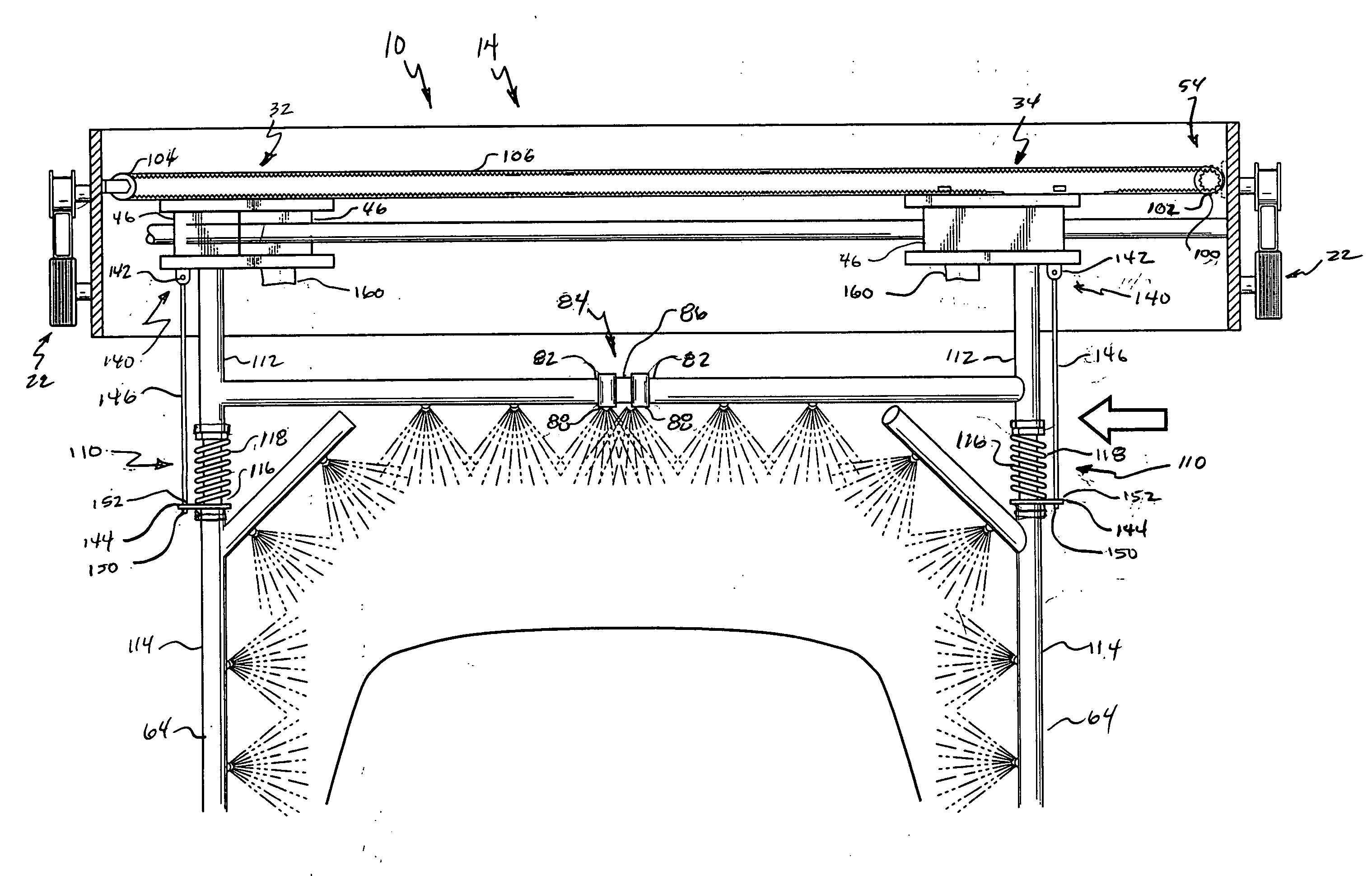
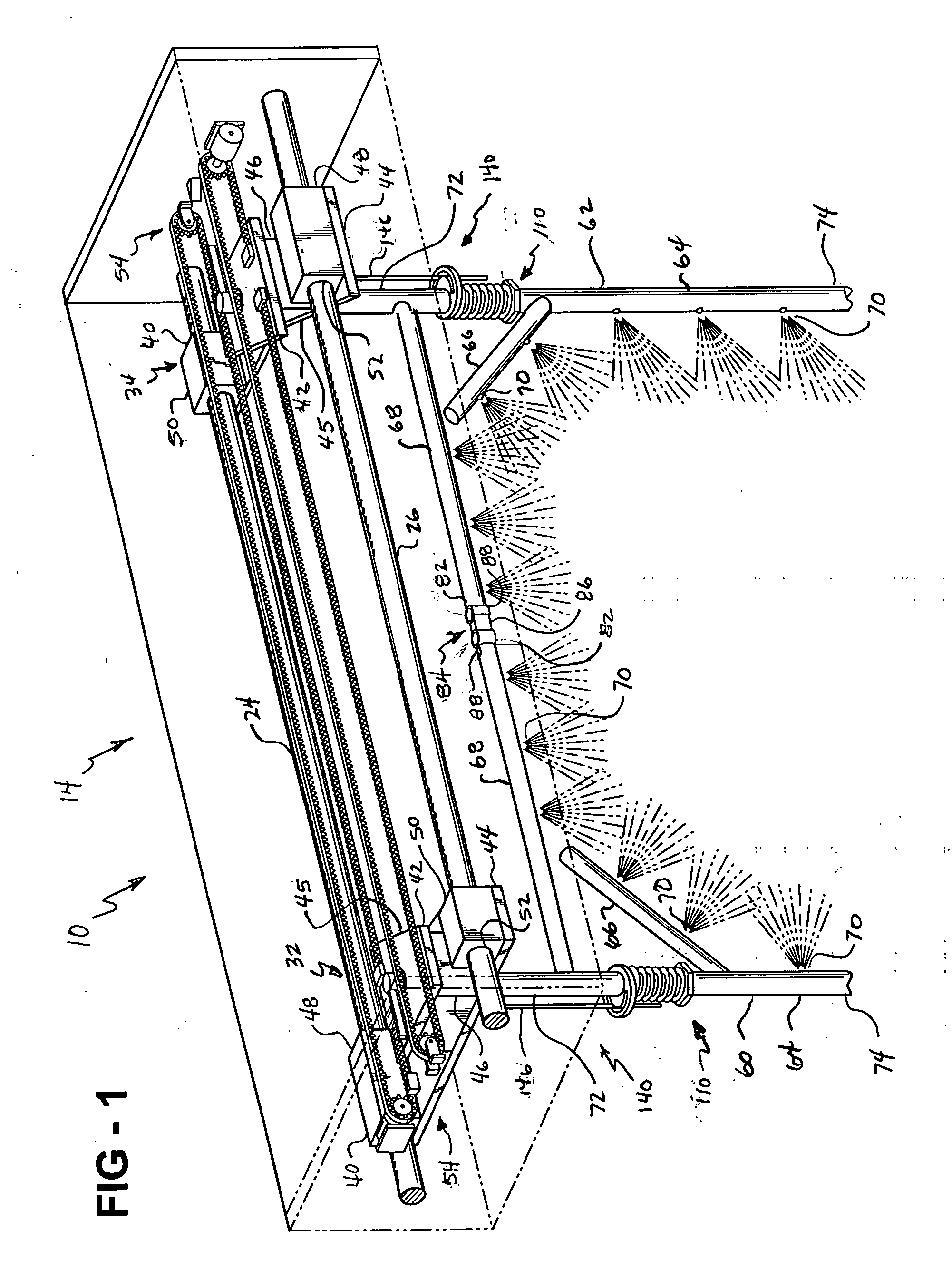
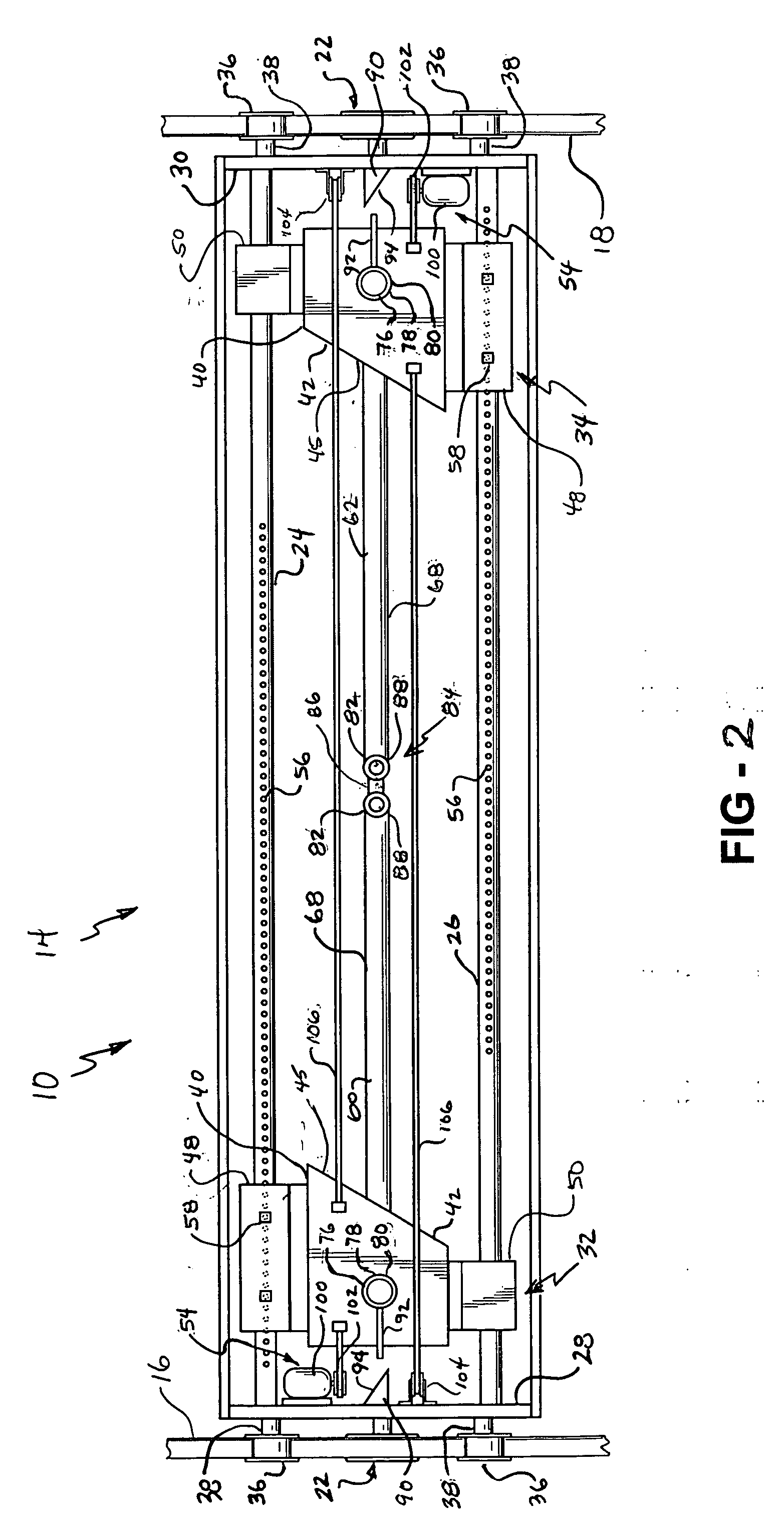
[0033] A vehicle wash apparatus of the present invention is generally indicated at 10 where like numerals are used to designate like structure throughout the figures. The vehicle wash apparatus 10 is a rollover type system having a carriage assembly adapted to be supported above a vehicle and moveable rectilinearly along the length thereof. Thus, the vehicle wash apparatus 10 includes an overhead carriage assembly generally indicated at 14. As shown in FIG. 2, a pair of spaced longitudinal carriage rails 16 and 18 are provide by a rigid frame assembly (not shown).

[0034] The carriage assembly 14 includes at least one carriage drive assembly, generally indicated at 22, a pair of shuttle rails 24, 26. It should be appreciated that the carriage assembly 14 may take on a variety of forms. For example, the carriage assembly 14 may be an enclosed housing, or simply a number of rigid pieces that form a structural framework. Regardless, for the purposes of discussion herein, the carriage a...


PUM


Abstract

A vehicle wash apparatus including a carriage assembly is supported above a vehicle. A pair of opposed shuttle assemblies are operatively supported by the carriage assembly and moveable generally transverse to the carriage assembly. A pair of spray manifold assemblies are operatively supported by one of the opposed shuttle assemblies, and each of the spray manifold assemblies includes a vertical manifold. Each of the pair of spray manifold assemblies are moveable rectilinearly with the carriage assembly, transversely with the shuttle assemblies, and pivotally about the vertical manifold to allow the pair of spray manifold assemblies to move toward and away from one another and to circumscribe the vehicle.

Description

BACKGROUND OF THE INVENTION [0001] 1. Field of the Invention [0002] The present invention relates, generally, to a vehicle wash apparatus and, more specifically, to a vehicle wash apparatus having a pair of spray arms adapted to move about the surface of the vehicle at an optimum cleaning distance. [0003] 2. Description of the Related Art [0004] Motor vehicles are washed and cleaned in order to preserve and extend the life of the vehicle finish and maintain its appearance. Automatic drive-through wash facilities that provide this service are well known. For example, traditional tunnel, conveyor-type wash facilities are common in this industry and typically employ an array of equipment that sequentially treats the vehicle as it passes through the facility. While these systems have generally worked for their intended purpose, the traditional tunnel systems occupy a considerable amount of space and often require a considerable amount of maintenance to keep the associated series of wash...

Claims


Application Information

Patent Timeline
IPC IPC(8): B08B3/00B08B3/12
CPCB05B1/205B05B13/0278B05B13/0405B05B15/066B60S3/04B05B15/652
Inventor BELANGER, MICHAEL
Owner BELANGER MICHAEL
Why Eureka
Try Eureka