Cooling device
a technology of cooling device and display device, which is applied in the direction of instruments, television systems, and semiconductor/solid-state device details, etc., can solve the problems of excessive draft resistance, limited luminance increase, and increase in the size of the apparatus but also to an increase in weight, so as to achieve efficient cooling of electronic devices
- Summary
- Abstract
- Description
- Claims
- Application Information
AI Technical Summary
Benefits of technology
Problems solved by technology
Method used
Image

Examples
first embodiment
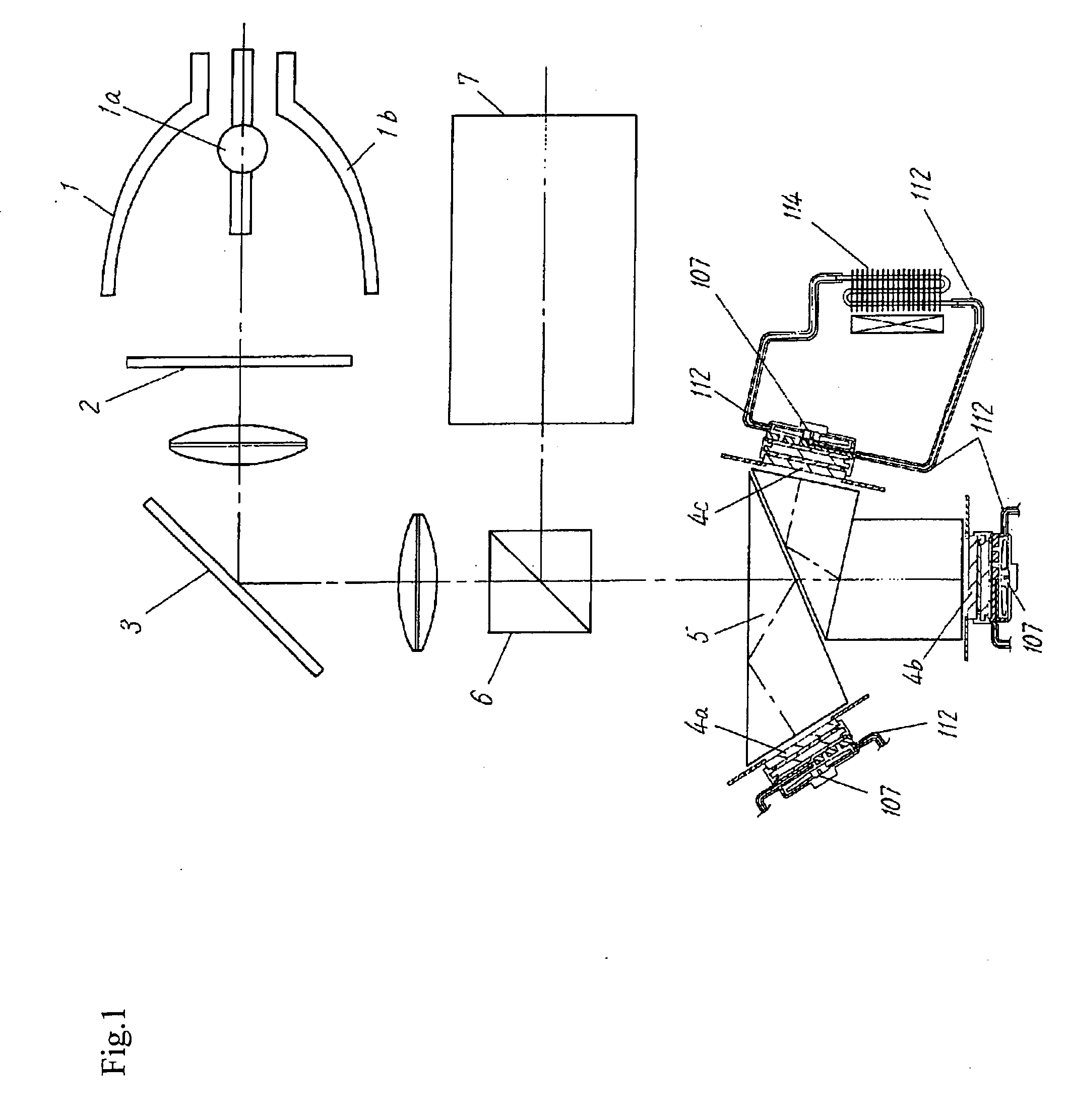
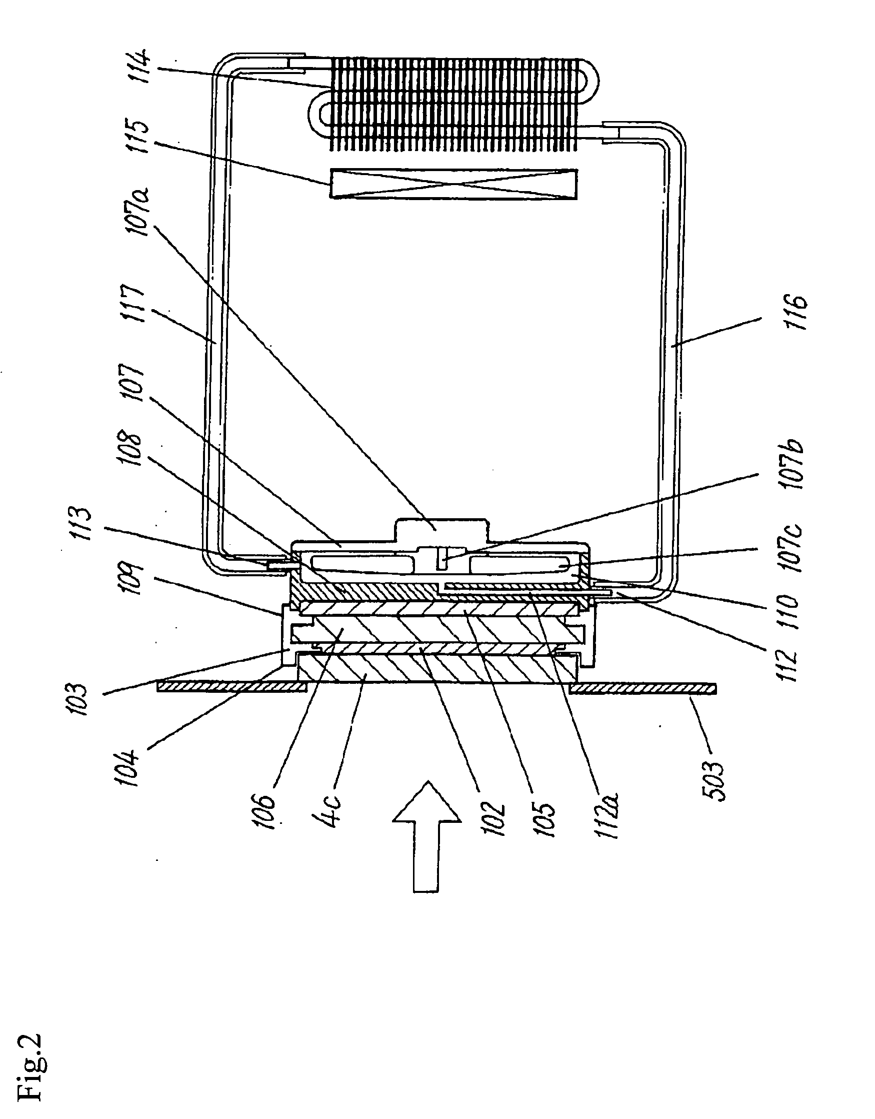
[0114] Hereunder, a configuration of a cooling apparatus according to this embodiment will be described by mainly referring to FIGS. 1 and 2.
[0115]FIG. 1 is a schematic block diagram of a projection display apparatus using the cooling apparatus according to the first embodiment of the present invention, and FIG. 2 is a schematic sectional view of the cooling apparatus according to the first embodiment of the present invention.
[0116] In FIGS. 1 and 2, portions of the same configuration as a conventional apparatus described by using FIGS. 10 and 11 are given the same symbols. These portions have the same functions, and so a detailed description thereof will be omitted.
[0117]FIG. 2 shows the cooling apparatus for the reflective display device 4c which is a heating element, where the cooling apparatuses corresponding to the reflective display device 4a and 4b also have the same functions.
[0118]4a, 4b and 4c denote the reflective display devices corresponding to red (R) green (G) and...
second embodiment
[0166] First, a description will be given by mainly referring to FIG. 3 as to the configuration and operation of the cooling apparatus according to this embodiment.
[0167]FIG. 3 is a schematic sectional view of the cooling apparatus according to the second embodiment of the present invention.
[0168] The cooling apparatus according to this embodiment is similar to that according to the first embodiment. Therefore, differences between them will be mainly described.
[0169] The cooling apparatus according to this embodiment has a plurality of openings 111 provided in a joining casing surface (one flat surface) of a heat receiving casing 1108 thermally joined to the electronic cooling element 105.
[0170] And the electronic cooling element 105 is directly contacted by the fluid medium 110 circulated inside the heat receiving casing 1108 through the openings 111.
[0171] Each of the plurality of openings 111 is circular for instance, and they are arranged like a matrix except a portion in w...
third embodiment
[0177] First, a description will be given by mainly referring to FIG. 4 as to the configuration and operation of the cooling apparatus according to this embodiment.
[0178]FIG. 4 is a schematic sectional view of the cooling apparatus according to the third embodiment of the present invention.
[0179] The cooling apparatus according to this embodiment is similar to that according to the aforementioned second embodiment. Therefore, the differences between them will be mainly described.
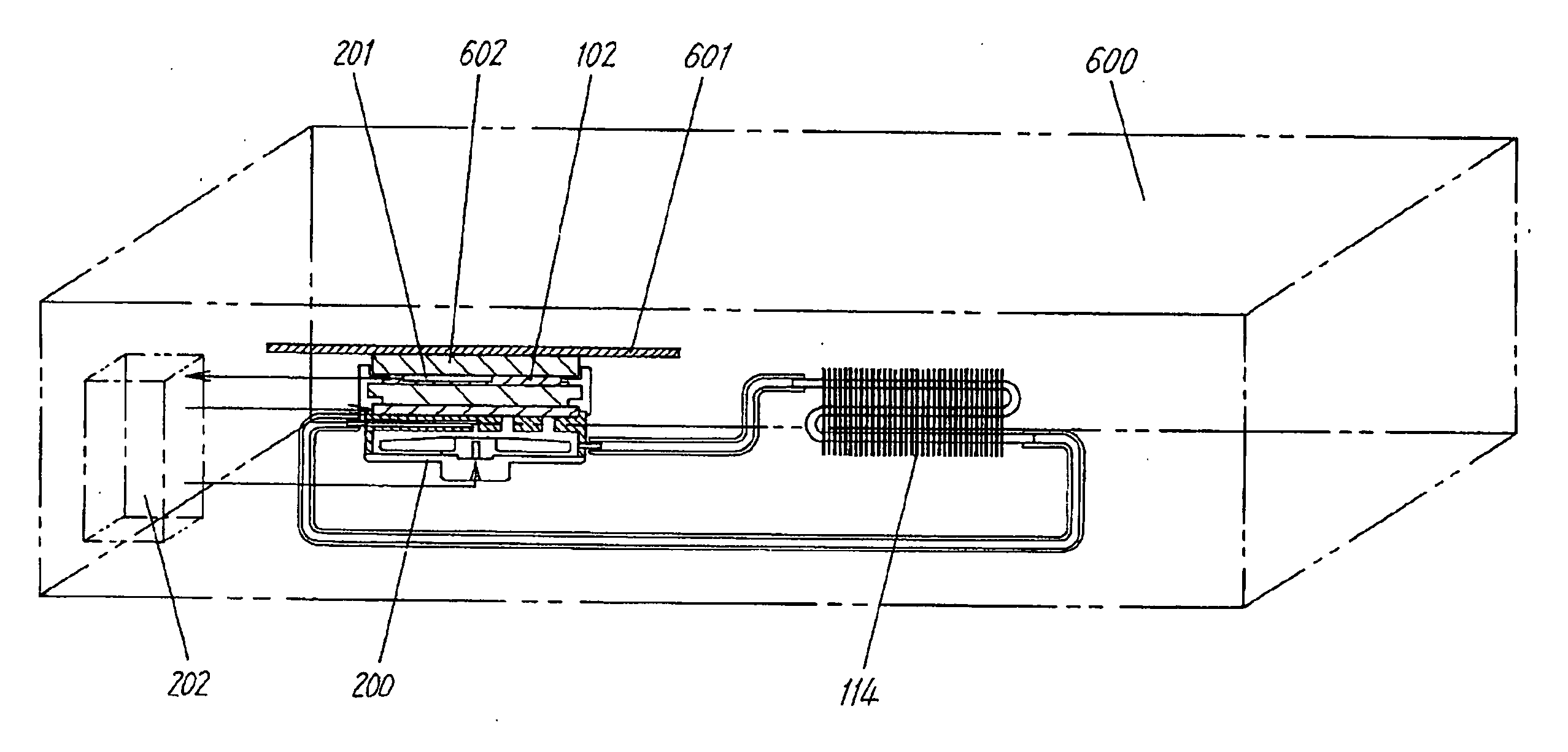
[0180] The cooling apparatus according to this embodiment is capable of temperature control.
[0181] To be more precise, temperature detection means 201 of detecting temperature of the reflective display device 4c as the heating object and converting it to an electrical signal is integrally built into the heat receiving plate 102.
[0182] And temperature control means 202 of controlling driving of the solution sending pump 107 and driving of the radiating fan 115 to the radiator 114 into an optimal state is...
PUM
 Abstract
Description
Claims
Application Information
 - Generate Ideas
- Intellectual Property
- Life Sciences
- Materials
- Tech Scout
- Unparalleled Data Quality
- Higher Quality Content
- 60% Fewer Hallucinations
Browse by: Latest US Patents, China's latest patents, Technical Efficacy Thesaurus, Application Domain, Technology Topic, Popular Technical Reports.
© 2025 PatSnap. All rights reserved.Legal|Privacy policy|Modern Slavery Act Transparency Statement|Sitemap|About US| Contact US: help@patsnap.com