Form liner for creating a realistic stone wall pattern

a technology of stone wall and form liner, which is applied in the field of wall structures, can solve the problems of inability to build such a wall, and high labor intensity of stone wall construction workers

Inactive Publication Date: 2006-07-20
NASVIK PAUL C
View PDF32 Cites 38 Cited by
  • Summary
  • Abstract
  • Description
  • Claims
  • Application Information

AI Technical Summary

Benefits of technology

[0012] The form liner of the present invention is used to create a simulated stone wall having a random pattern while masking the horizontal or vertical connections. The form liner comprises an outer edge and a surface formed by reverse impression that is contoured to resemble a plurality of stones held together by an adhesive substance. The outer edge of the form liner has a first, second, third, fourth, fifth, and sixth connection region. Each connection region is non-linear and made of multiple segments. In placing a plurality of form liners adjacent one another to form a wall, each connection region of a form liner mates with only one corresponding connection region of an adjacent form liner. No linear segment defining the fifth connection region follows the same linear path as any linear segment defining the sixth connection region.

Problems solved by technology

Although a wall comprised of individual stones may be desirable, building such a wall is not always a practical option.
Constructing a wall made of stone is often labor intensive and requires highly skilled laborers.
In addition, the costs of the materials themselves are high, and the cost of the labor involved is likewise high.
However, forming a simulated stone wall using several form liners to create the stone pattern has been impractical to date.
In addition, it is difficult to mask the joint created where adjacent form liners meet, which may result in the ability to determine the location of each form liner on the finished wall, which in turn makes the wall more obviously simulated rather than realistic.
However, the greater the number of form liners required to achieve a random appearance, the greater the cost of the finished wall.
Two problems are frequently encountered when a form liner is repeated in a continuous structure.
The first problem arises due to the manner in which the form liners are arranged next to each other on the form.
Such multi-sided form liners increases the complexity of manufacturing the wall, because the form liners must be carefully arranged on the form to ensure they fit next to each other properly and in the most efficient manner.
A second problem arises because the human eye is proficient at identifying repeating patterns.
This problem is particularly true of simulated natural and cut stone walls because in a real stone wall, every stone surface is unique.
The ability to rotate the form liner and still fit it to an adjacent form liner reduces the number of form liners required to obtain a suitably random appearing wall because merely inverting the stones makes them much more difficult for the human eye to recognize even when the pattern is repeated.
However, such form liners may still result in obvious horizontal or vertical joint locations, and may only minimize, rather than eliminate, the ability to recognize repeating patterns in the finished wall.

Method used


Image

  • Form liner for creating a realistic stone wall pattern
  • Form liner for creating a realistic stone wall pattern
  • Form liner for creating a realistic stone wall pattern

Examples


first embodiment

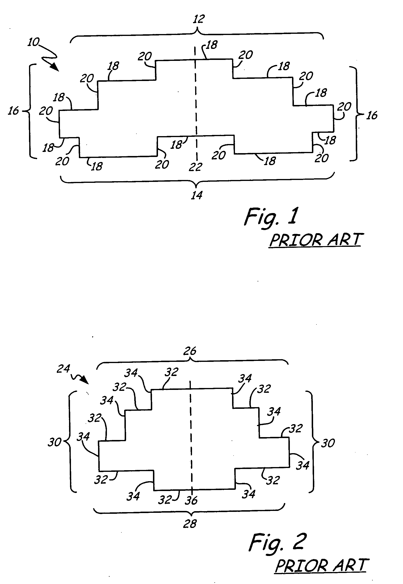
[0031]FIGS. 1 and 2 represent two different embodiments of prior art form liners. FIG. 1 shows a front view of a prior art form liner 10. Prior art form liner 10 comprises top region 12, bottom region 14, and side regions 16 made of twenty horizontal segments 18 and vertical segments 20 connected to each other at ninety degree angles with relatively long linear top and bottom regions 12 and 14. Prior art form liner 10 has an axis of symmetry 22 which results in prior art form liner 10 having “mirror” symmetry.

[0032] When several prior art form liners 10 are placed adjacent to one another to pour a wall, the relatively long linear top and bottom regions 12, 14 tend to align in rows. The rows created by the top and bottom regions 12, 14 may become discernible to the human eye. Repeating patterns which are easily discernible are less desirable because it is more obvious the resulting wall is simulated, rather than made of unique individual components.

second embodiment

[0033]FIG. 2 shows a front view of a prior art form liner 24. Prior art form liner 24 comprises top region 26, bottom region 28, and vertical regions 30 made of sixteen horizontal and vertical segments 32 and 34 connected to each other at ninety degree angles with relatively long linear top and bottom regions 26 and 28. Prior art form liner 22 also has an axis of symmetry 36 which results in prior art form liner 24 having “mirror” symmetry. Though less obvious, the prior art form liners 24 may also cause horizontal rows to appear in a wall formed from several form liners 24 arranged next to each other on a form.

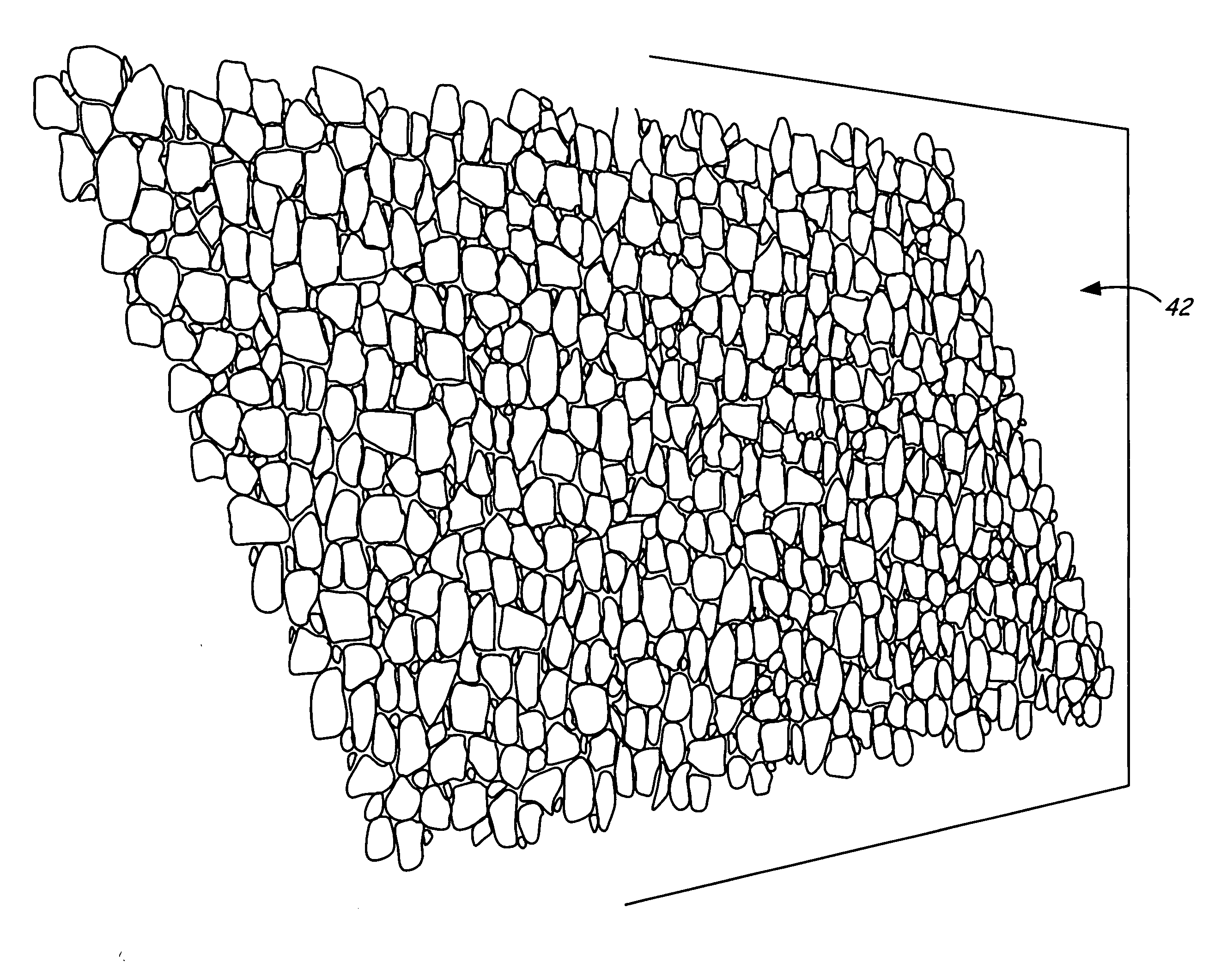
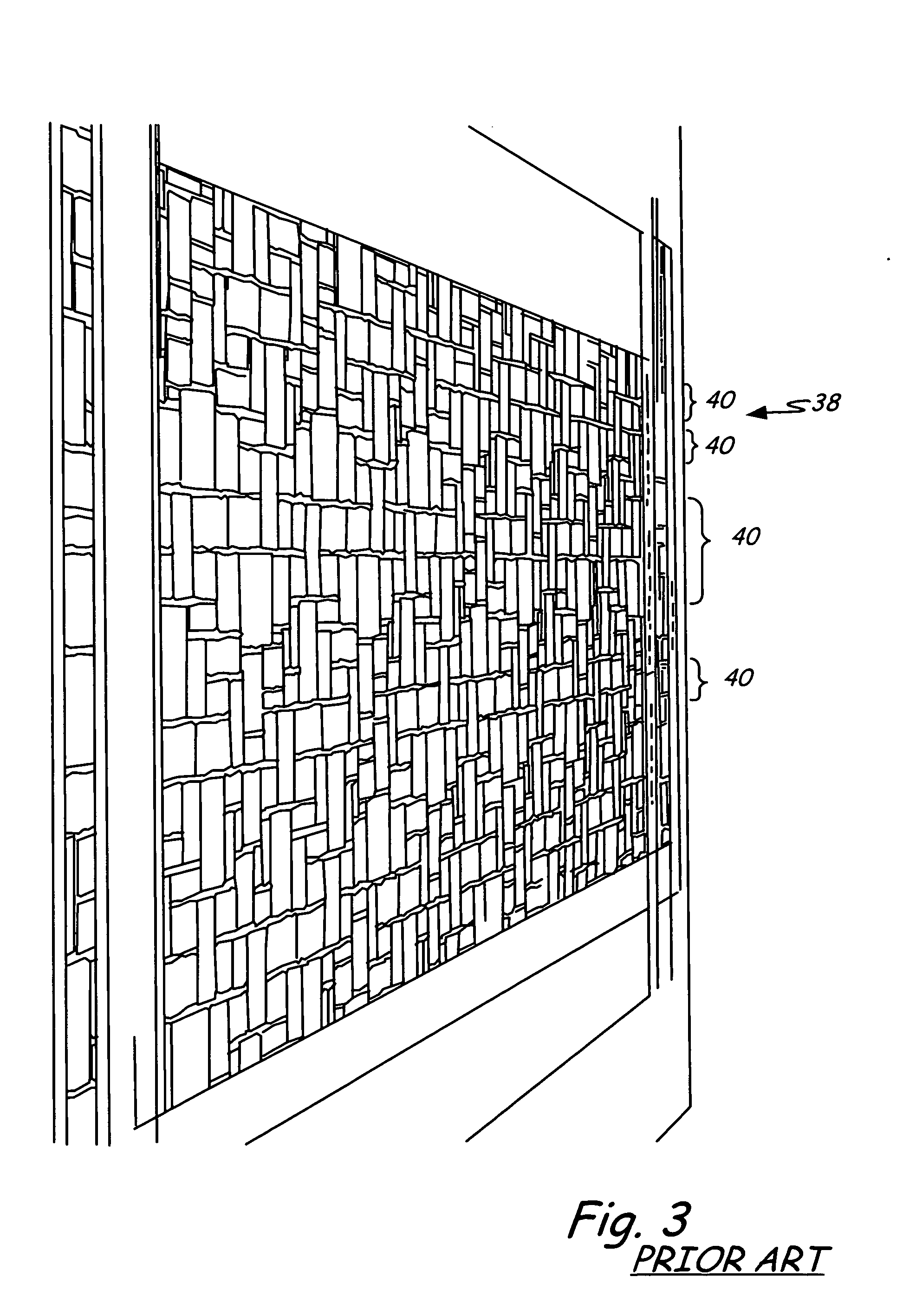
[0034]FIG. 3 is a perspective view of a simulated stone wall 38 constructed from a plurality of prior art form liners similar to those illustrated in FIG. 1. As can be seen in FIG. 3, particularly when the simulated stone wall 38 is viewed from an angle, horizontal lines 40 become visible to the human eye. In part, the horizontal lines 40 are visible due to the generally line...


PUM


Abstract

The form liner of the present invention simulates a natural stone wall having a random pattern. The form liner comprises an outer edge and a surface that is contoured to resemble a plurality of stones held together by an adhesive substance. The outer edge of the form liner has six connection regions made up of multiple linear segments. No two adjacent connection regions are connected at a ninety degree angle and no linear segment of the fifth connection region lies along the same linear path as any linear segment of the sixth connection region.

Description

BACKGROUND OF THE INVENTION [0001] The present invention relates generally to wall structures constructed from hardenable material, such as concrete. In particular, the present invention relates to concrete walls that are constructed from form liners which can be placed next to one another to form a wall surface which resembles a wall made from stones. [0002] Wall structures can be constructed from a single uniform building material such as concrete or drywall, or from unique individual building materials such as natural stones, cut stones, or bricks that are bonded together with an adhesive substance, such as mortar. When a continuous wall structure is formed from a uniform building material, the surface of the wall will typically have a smooth surface. By contrast, when a continuous wall structure is formed by arranging individual building materials relative to each other and maintaining them in place with an adhesive substance, the surface of the wall can have a random pattern, w...

Claims


Application Information

Patent Timeline
Patent Type & Authority Applications(United States)
IPC IPC(8): E04G9/10
CPCB28B7/0073B28B7/36E04G9/10
Inventor NASVIK, PAUL C.
Owner NASVIK PAUL C
Why Eureka
Try Eureka