Lamp-lighting apparatus

a technology of lamplighting and lamp body, which is applied in the direction of electric variable regulation, process and machine control, instruments, etc., can solve the problems of excessive discharge tube, part rating, shape and cost, etc., and achieve the effect of reducing the cost of the devi

Active Publication Date: 2006-07-20
TAIYO YUDEN KK
View PDF8 Cites 13 Cited by
  • Summary
  • Abstract
  • Description
  • Claims
  • Application Information

AI Technical Summary

Benefits of technology

[0012] Accordingly, it is an object of the present invention to provide a technique for reducing the cost of a device for lighting a lamp such as a discharge tube.

Problems solved by technology

In this case, the following problems regarding shape and cost arise.
(2) The voltage produced at the junction of the shunt transformer TB100 and the discharge tube becomes excessively high.
Consequently, it is necessary to increase the interconnect pattern spacing, part ratings, and so on excessively.
The prior art technique presents problems in terms of cost for the reason described above.

Method used


Image

  • Lamp-lighting apparatus
  • Lamp-lighting apparatus
  • Lamp-lighting apparatus

Examples


first embodiment

A. First Embodiment

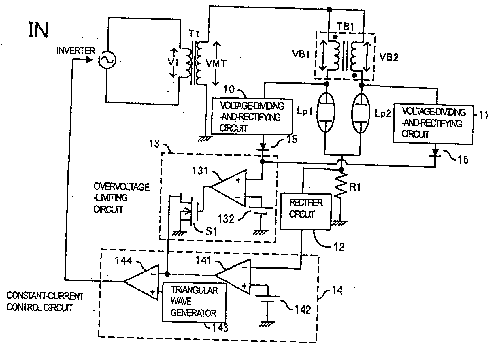
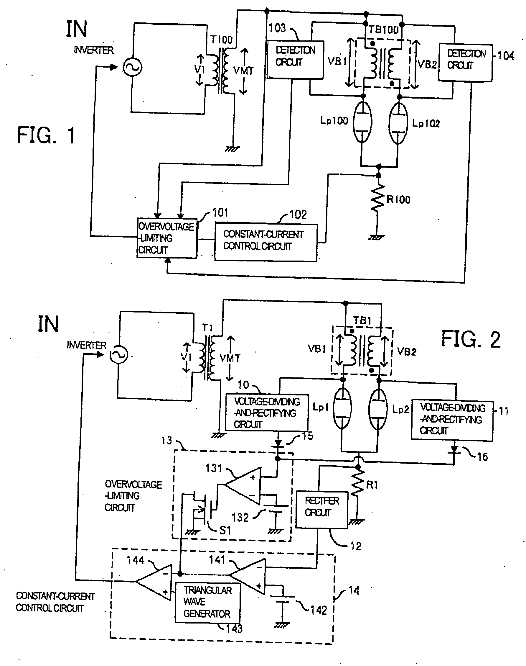
[0049] An example of circuit of a lamp-lighting apparatus associated with a first embodiment of the present invention is shown in FIG. 2. This lamp-lighting apparatus has an inverter including a switching circuit, an inverter transformer (main transformer) T1, a shunt transformer (balancer) TB1, lamps Lp1 and Lp2 such as cold-cathode tubes, a resistor R1, voltage-dividing-and-rectifying circuits 10 and 11, a rectifier circuit 12, an. overvoltage-limiting circuit 13, a constant-current control circuit 14, and diodes 15, 16. The overvoltage-limiting circuit 13 has a comparator 131, a first reference voltage source 132, and a MOSFET S1. The constant-current control circuit 14 has comparators 141, 144, a second reference voltage source 142, and a triangular wave generator 143.

[0050] The inverter is connected with the primary winding of the inverter transformer T1. A voltage V1 is applied to the primary winding of the inverter transformer T1. A voltage VMT is produced...

second embodiment

B. Second Embodiment

[0063] An example of circuit of a lamp-lighting apparatus associated with a second embodiment of the present invention is shown in FIG. 5. This lamp-lighting apparatus associated with the second embodiment is a modification of the lamp-lighting apparatus associated with the first embodiment and similar to the first embodiment except that the balancer 17 of FIG. 5 is different from the balancer of the first embodiment. The balancer 17 includes transformers TB1a and TB1b which produce voltages on the secondary winding side such that the voltages on the primary and secondary sides are in phase. A first terminal of the primary winding of the transformer TB1a is connected with a first terminal of the secondary winding of the inverter transformer T1. A second terminal of the primary winding of the transformer TB1a is connected with the first terminal of the lamp Lp1 and with the input terminal of the voltage-dividing-and-rectifying circuit 10. Similarly, a first termin...

third embodiment

C. Third Embodiment

[0065] An example of circuit of a lamp-lighting apparatus associated with a third embodiment of the present invention is shown in FIG. 6. This lamp-lighting apparatus associated with the third embodiment is a modification of the lamp-lighting apparatus associated with the first or second embodiment. In the present embodiment, the primary windings of transformers TB1c and TB1d are connected with the lamps. The secondary windings form a closed loop. The transformers further include tertiary windings to detect voltages produced on the primary windings. The transformers TB1c, TB1d, diodes 20a, 20b connected with the tertiary windings of the transformers TB1c, TB1d, a voltage-dividing-and-rectifying circuit 18, and a voltage-adding circuit 19 are mounted instead of the shunt transformer TB1 of FIG. 2 or instead of the balancer 17, the voltage-dividing-and-rectifying circuits 10, 11 and the diodes 15, 16 of FIG. 5. The transformers TB1c and TB1d produce voltages on the ...


PUM


Abstract

An economical device for lighting lamps such as discharge tubes. The lamp-lighting apparatus has an inverter transformer, a switching circuit connected with the primary winding of the inverter transformer and acting to perform switching for converting a voltage from an input power supply, a shunt transformer connected in series with the secondary winding of the inverter transformer, lamps connected in series with the shunt transformers, and a control circuit for producing a control signal to control the switching performed by the switching circuit based on the voltages at the junctions of the shunt transformer and each of the lamps without directly detecting the voltage applied to the secondary winding of the inverter transformer. The number of protective circuits can be reduced. Consequently, the cost can be reduced.

Description

BACKGROUND OF THE INVENTION [0001] The present invention relates to a lamp-lighting apparatus. [0002] Background Art [0003] One example of the prior art discharge tube-lighting device is shown in FIG. 1. In the lighting device of FIG. 1, a voltage V1 is applied across the primary winding of a main transformer T100 by an inverter including a switching circuit. A voltage VMT is induced across the secondary winding of the main transformer T100. One end of the secondary winding of the main transformer T100 is connected to respective one ends of the primary and secondary windings of a shunt transformer (balancer) TB100. The other end of the secondary winding of the main transformer T100 is grounded. One end of a discharge tube Lp100 such as a cold-cathode tube is connected to the other end of the primary winding of the shunt transformer TB100. One end of a discharge tube Lp102 is connected to the other end of the secondary winding of the shunt transformer TB100. The shunt transformer TB1...

Claims


Application Information

Patent Timeline
Patent Type & Authority Applications(United States)
IPC IPC(8): B60Q1/02
CPCH05B41/2851H05B41/36H05B41/26
Inventor HOSAKA, YASUOKONNO, YOSHIHISA
Owner TAIYO YUDEN KK
Why Eureka
Try Eureka