Motion actuator

a technology of motion actuator and actuator shaft, which is applied in the direction of pulse manipulation, pulse technique, instruments, etc., can solve the problems of shaft rotation along its axis, unadjustable clamping and unclamping motion, etc., and achieve the effect of preventing undeired rotation facilitating the machining of the object to be moved

Inactive Publication Date: 2006-07-20
ACAD SINIC
View PDF10 Cites 6 Cited by
  • Summary
  • Abstract
  • Description
  • Claims
  • Application Information

AI Technical Summary

Benefits of technology

[0007] Another objective of this invention is to provide a compact and rigid motion actuator.
[0008] Another objective of this invention is to provide a motion actuator with an adjusting mechanism whereby machining of object to be moved is made easier.

Problems solved by technology

However, the outer surface of the movable shaft and the surfaces of the two clamps that make contact with the shaft have to be machined with precision and accuracy better than 10

Method used


Image

  • Motion actuator
  • Motion actuator
  • Motion actuator

Examples


Embodiment Construction

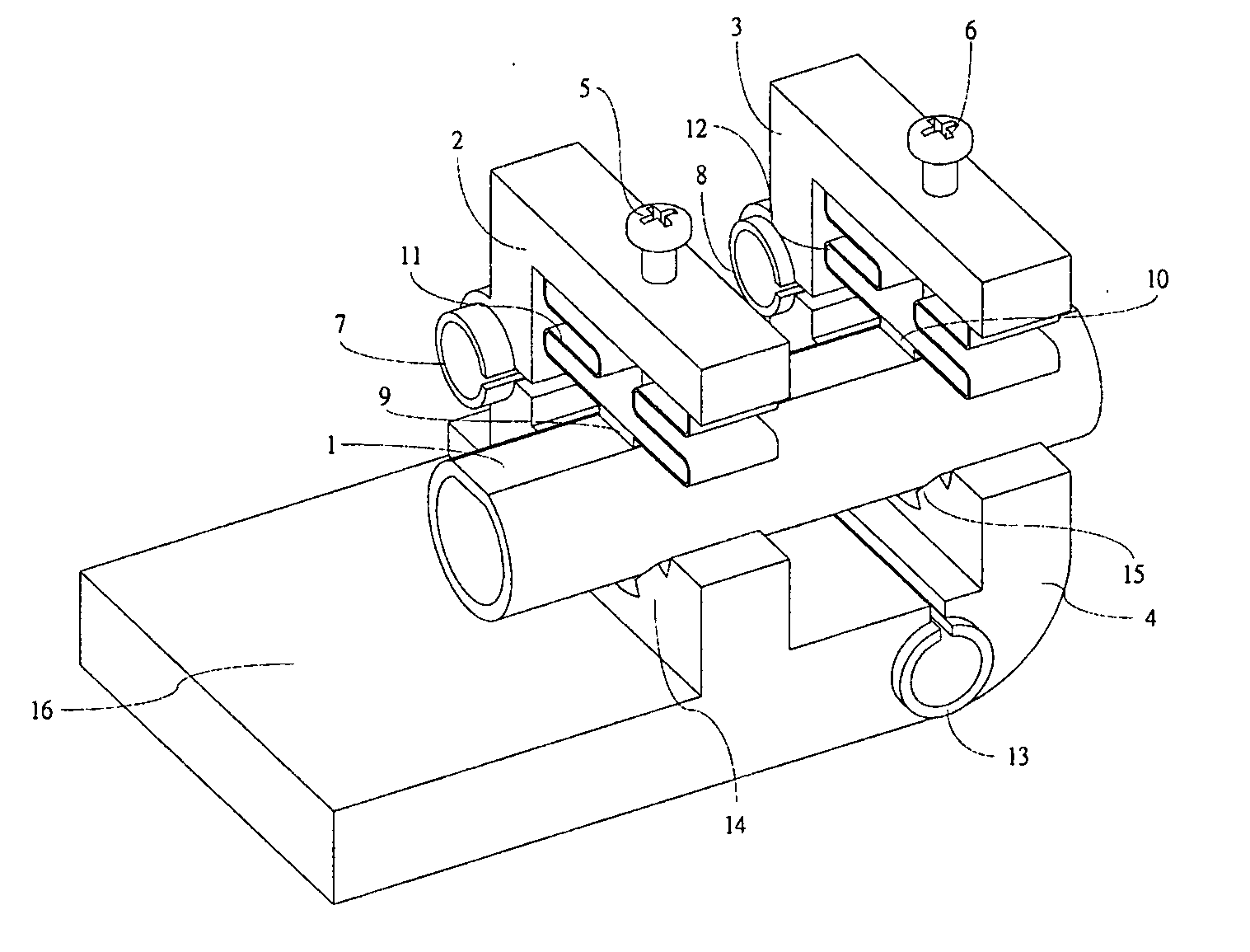
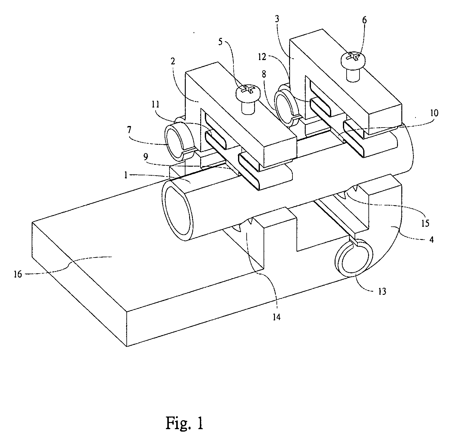
[0017] The motion actuator of this invention comprises a cylindrical movable shaft and a main body to drive the movable shaft. The main body which comprises a stage, as well as an expansible / contractible device and two clamps, can be made out of a single piece of a ceramic material, such as MACOR, or a hard metallic material, such as stainless steel. Stainless steel is preferred, because it allows the machining with an electrical discharge machine.

[0018]FIG. 1 shows the structure of one embodiment of the motion actuator of this invention. As shown in this figure, the motion actuator of this invention has a main body to drive a movable shaft 1. The main body comprises a stage 16 which has two clamps 2 and 3 that can be controlled to grip the movable shaft, and an expansible / contractible device 4 for driving the movable shaft 1. Denoted at 7 and 8 are actuators that control the grip of the movable shaft 1 by the two clamps 2 and 3, respectively. The expansible / contractible device 4 i...


PUM


Abstract

A motion actuator comprises a cylindrical movable shaft and a stage that contains an expansible/contractible device and two clamps. The expansible/contractible device can be controlled to drive the axial motion of the movable shaft, and the two clamps can be controlled to grip/release the shaft. The two clamps and the expansible/contractible device are each controlled by a bimorph structure, which comprises a cut cylindrical piezoelectric tube section in a hole enclosed by a thin wall in the stage. By sequentially activating the three piezoelectric tube sections, axial motions of the movable shaft relative to the stage in small steps are made. Each of the two clamps can be adjusted by a screw, which presses a spring structure that makes contact with the top surface of the movable shaft, so that the clamps can grip the movable shaft firmly when actuated, but not when not actuated. The flat top surface of the movable shaft is designed to inhibit the possible rotation along its axis during its axial motion. The shaft is supported by two lines at the bottom of each of the two clamps to reduce the contact area, which improves the reliability of the motion.

Description

FIELD OF THE INVENTION [0001] The present invention relates to a motion actuator, especially to a long distance linear motion actuator. BACKGROUND OF THE INVENTION [0002] In nanotechnology, one of the key techniques is to achieve fine positioning with a sub-micrometer resolution. For example, in scanning probe microscopy, the probe has to be brought close to a sample from a few mm apart to within a distance of only a few nanometers. There are many other applications wherein fine positioning and motion of articles are required. [0003] An early type of a piezoelectric inchworm motor was disclosed by William G. May, Jr., in his U.S. Pat. No. 3,902,084, “Piezoelectric electromechanical translation apparatus” (assigned to Burleigh Instruments, Inc.). Later, H. Atsushi et al. disclosed a modification to May's invention in their U.S. Pat. No. 4,570,096, “Electromechanical translation device comprising an electrostrictive driver of a stacked ceramic capacitor type” (assigned to NEC Corporat...

Claims


Application Information

Patent Timeline
IPC IPC(8): G01N30/86
CPCH02N2/023
Inventor HWANG, ING-SHOUHHUNG, SHAO-KANGTIN, CHENG-SHINGHU, AND DE
Owner ACAD SINIC
Why Eureka
Try Eureka