Eureka AIR delivers breakthrough ideas for toughest innovation challenges, trusted by R&D personnel around the world.

Plasma display panel driving method and plasma display apparatus

a technology of plasma display panel and driving method, which is applied in the direction of gas discharge vessel/container, address electrode, instruments, etc., can solve the problems of reducing the life of phosphor materials, and achieve the suppression of characteristic deterioration of phosphor layers, improved light-emission efficiency in display discharge, and the effect of improving the light-emission efficiency

Inactive Publication Date: 2006-07-20
HITACHI LTD
View PDF4 Cites 7 Cited by
  • Summary
  • Abstract
  • Description
  • Claims
  • Application Information

AI Technical Summary

Benefits of technology

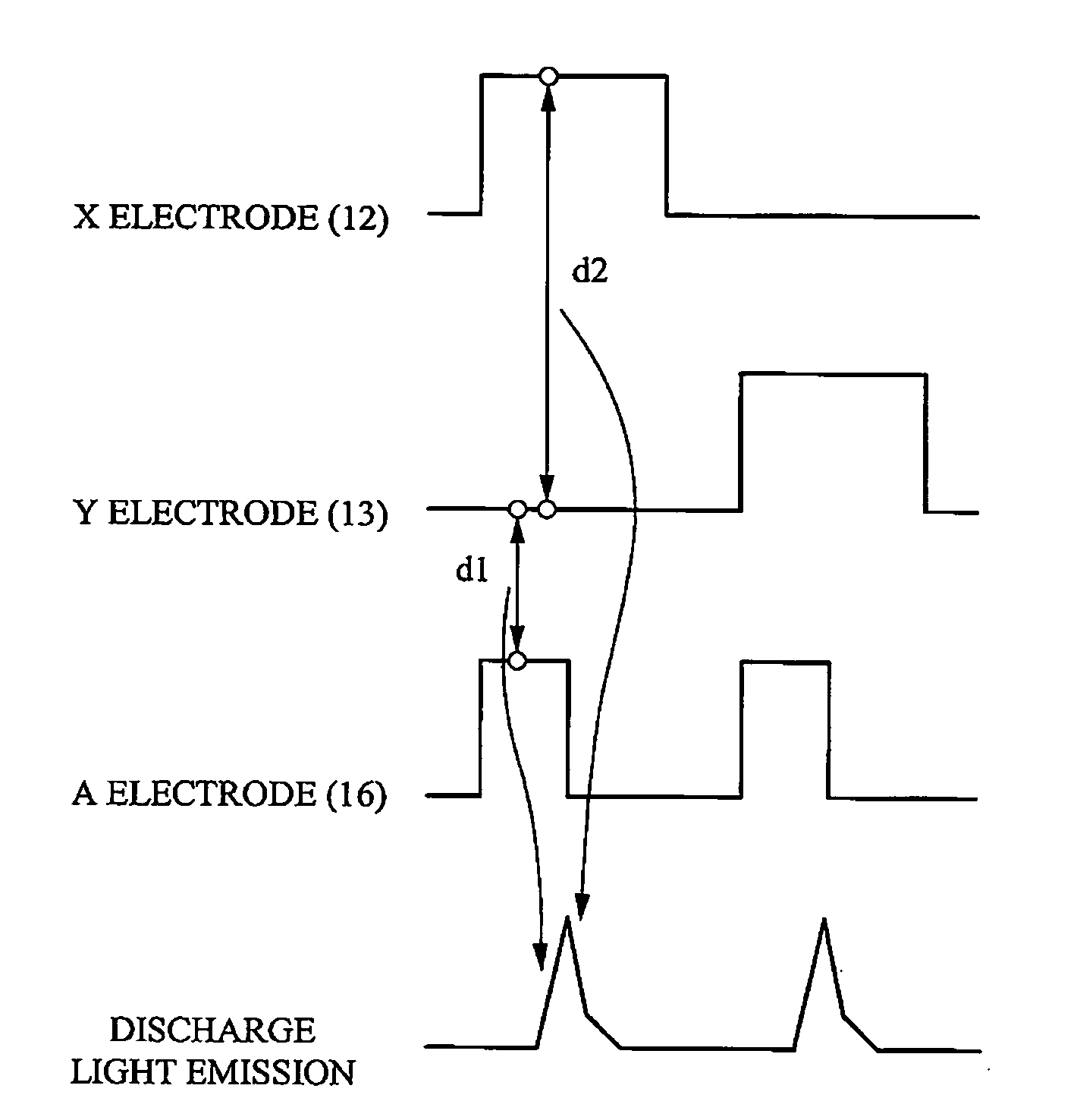
[0028] That is, as shown in FIGS. 4 and 5, in the conventional plasma display driving method, the short pulse voltage is given to the A electrode and the auxiliary discharges (micro discharges: d1) are generated between the A electrode 16 and the Y electrode 13 and between the A electrode 16 and the X electrode 12, whereby the luminance and the light-emitting efficiency in the main discharge (display discharge: d2) between the X electrode 12 and the Y electrode 13 have been improved.
[0031] In consideration of the above-described problems of the plasma display panel driving method and the plasma display apparatus, an object of the present invention is to improve the luminance and the light-emission efficiency in the display discharge and suppress the characteristic deterioration of the phosphor layer.
[0034] According to the present invention, the luminance and the light-emission efficiency in the display discharge can be improved and the characteristic deterioration of the phosphor layer can be suppressed.

Problems solved by technology

Therefore, there is a problem that the phosphor layer 18 is exposed to the discharge and its characteristic deteriorates (reduction in life of the phosphor material).

Method used


Image

  • Plasma display panel driving method and plasma display apparatus
  • Plasma display panel driving method and plasma display apparatus
  • Plasma display panel driving method and plasma display apparatus

Examples


Embodiment Construction

[0054] With reference to the accompanying drawings, embodiments of a plasma display panel driving method and a plasma display apparatus according to the present invention will be described in detail below.

[0055]FIG. 6 is a view schematically showing an electrode structure of one cell of a plasma display apparatus according to one embodiment of the present invention. FIG. 7 is a view schematically showing driving waveforms of a display discharge in the plasma display apparatus according to one embodiment of the present invention.

[0056] As evident from a comparison between FIGS. 6 and 4, a display cell 10 of the plasma display apparatus according to the present embodiment is provided with a Z electrode 20 between an X electrode 12 and a Y electrode 13, unlike the conventional cell described with reference to FIG. 4. That is, the cell 10 is configured so as to include four electrodes, i.e., the X electrode 12, the Z electrode 20, and the Y electrode 13 provided on a front-side substr...


PUM


Abstract

In a conventional method of driving a plasma display panel, for example, an auxiliary discharge is executed between an A electrode and a Y electrode to improve light-emission efficiency of a display discharge. However, since a phosphor layer is present between the A electrode and the Y electrode, the phosphor layer is exposed to a discharge, whereby there is a problem that its characteristic deteriorates. A method of driving a plasma display panel having a structure, in which at least three display electrodes X, Y, and Z used for a display discharge are provided to a display cell and no phosphor layer is formed between said display electrodes and a discharge space, the method comprising the steps of: varying a potential of at least one display electrode Z of said display electrodes during said display discharge; and making a potential of said at least one display electrode Z at a time of starting said display discharge different from that at a time of ending said display discharge.

Description

CROSS-REFERENCE TO RELATED APPLICATION [0001] The present application claims priority from Japanese patent application No. JP 2004-377477 filed on Dec. 27, 2004, the content of which is hereby incorporated by reference into this application. BACKGROUND OF THE INVENTION [0002] The present invention relates to a driving method for a plasma display panel (PDP) and a plasma display apparatus. [0003] In recent years, an AC plasma display apparatus for executing a surface discharge has been commercially available as a flat-type display apparatus, and has been used as a display apparatus for personal computer and work station, etc., a flat-type wall-mounted television, and an apparatus for displaying advertisements, information, and others. Such a plasma display apparatus for executing the surface discharge has a structure in which a pair of electrodes is formed on an inner surface of a front glass substrate and an inert gas is enclosed therein, so that when a voltage is applied between th...

Claims


Application Information

Patent Timeline
Patent Type & Authority Applications(United States)
IPC IPC(8): G09G3/28G09G3/20G09G3/288G09G3/291G09G3/294G09G3/296G09G3/298G09G3/299H01J11/14H01J11/22H01J11/24H01J11/26H01J11/34
CPCG09G3/294G09G3/2986G09G3/299G09G2360/16G09G3/291G09G3/296
Inventor HASHIMOTO, YASUNOBUKISHI, TOMOKATSUSAKAMOTO, TETSUYAITOKAWA, NAOKIKOBAYASHI, TAKAYUKIKAWANAMI, YOSHIMITOYODA, OSAMUKUNII, YASUHIKOTAKAMORI, TAKAHIROTAKAYAMA, KUNIO
Owner HITACHI LTD
Why Eureka
Eureka Blog
Learn More