Remote viewing apparatus

a remote viewing and apparatus technology, applied in the field of remote viewing apparatuses, can solve the problems of requiring advance booking of both lift out and diver options, difficulty in checking the need for repair or routine maintenance, and similar difficulties, and achieve the effect of avoiding bending

Inactive Publication Date: 2006-07-20
DIGWEED ANTONY +1
View PDF0 Cites 26 Cited by
  • Summary
  • Abstract
  • Description
  • Claims
  • Application Information

AI Technical Summary

Benefits of technology

[0003] To mitigate the difficulties of the prior art the present invention provides a remote viewing apparatus including a waterproof camera connected to a remote screen which receives video signals from the camera. To position the camera at the required location the invention provides an elongate pole to which the camera is attached. For convenience in use, in reaching the required location, as well as for convenience in storage when not in use, the pole is telescopic and capable of being locked at variable lengths against further changes in length. Importantly, according to the present invention the camera is attached to the end of the pole by a pliable connector which can readily be bent by hand and retain a required curvature. Thus, the camera can be position at precisely the required location and angle of view for optimum inspection of the object of interest.

Problems solved by technology

Particularly for objects normally immersed in water, such as the hulls of boats, there is some difficulty in checking the need for repair or routine maintenance.
Both the lift out and diver options are costly and require advance booking, often involving a delay of at least several weeks.
Similar difficulties arise in other areas, such as in the inspection of decay to the underwater portion of lock gates.

Method used


Image

  • Remote viewing apparatus
  • Remote viewing apparatus
  • Remote viewing apparatus

Examples


Embodiment Construction

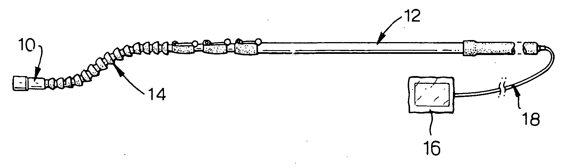
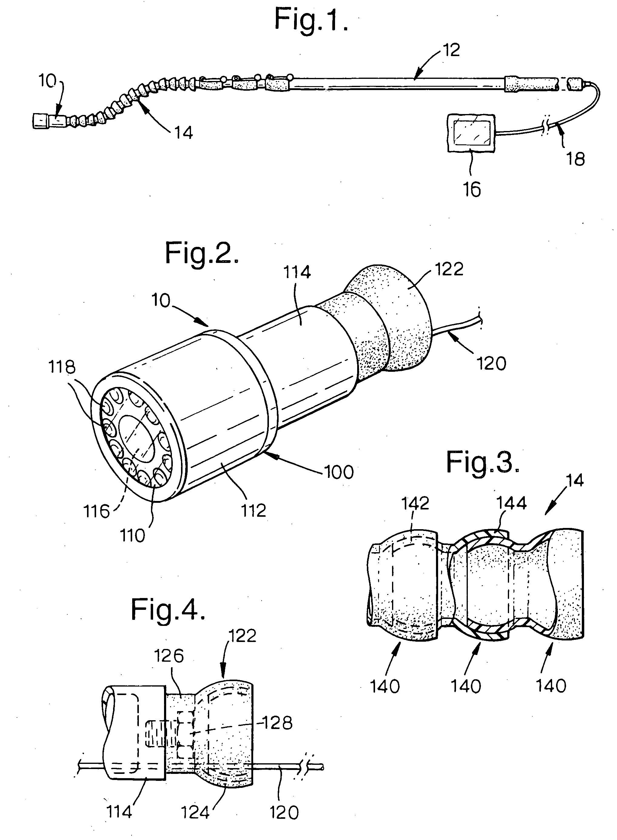
[0018]FIG. 1 illustrates the basic components of the preferred embodiment of the present invention. A camera 10 is attached to a telescopic pole 12 by a pliable connector 14. A monitor 16 receives video signals from the camera 10 via a cable 18.

[0019] The detail of the preferred arrangement of the camera 10 will now be described, with reference to FIG. 2. The camera 10 comprises a waterproof housing 100 having a transparent screen 110 at the front thereof. Generally the housing 100 has the form of a larger diameter cylinder 112 with a smaller diameter cylinder 114 projecting from the flat rear surface thereof. The larger, front cylinder houses a camera lens 116 surrounded by a plurality of white light LEDs 118. In use the lens 116 receives light from the LEDs 118, as well as ambient light, reflected from the object of interest. This is particularly useful in a marine environment where the underwater visibility may be restricted. In tests it has been found that sufficient illuminati...


PUM


Abstract

A remote viewing apparatus comprising: a monitor which operatively displays a picture using a video signal; a telescopic pole; and a unit including a camera which operatively outputs a video signal to be used by the monitor; a waterproof camera housing in which the camera is enclosed; a wand which is releasably retained at one end of the telescopic pole; and a pliable mechanical connector which connects the camera housing to the wand and which can be reversibly bent by hand to, and retain, a curved shape. A plurality of interchangeable units can be provided with additional units having the pliable connector bifurcated in to two arms with the camera housing being provided on one of the arms and an auxiliary device provided on the other of the arms. Examples of auxiliary devices are light sources and magnets.

Description

FIELD OF INVENTION [0001] The present invention relates to a remote viewing apparatus, one non-limiting application of which is for the underwater inspection of the hull, propellers and the like of leisure boats. BACKGROUND ART [0002] Particularly for objects normally immersed in water, such as the hulls of boats, there is some difficulty in checking the need for repair or routine maintenance. For example, boats normally carry on the outside of the hull, underwater a so-called sacrificial anode. Such an anode is corroded by electrolysis as a result of leakage from the boats electrical supply and is designed as the weakest part of the system; so that it corrodes rather than other underwater metallic parts of the boat particularly the propellers. Conventionally the sacrificial anode is checked for the need to replace it when the boat is lifted out of the water, which is often undertaken once a year for general maintenance purposes. Alternatively a diver can be sent down for an underwa...

Claims


Application Information

Patent Timeline
Patent Type & Authority Applications(United States)
IPC IPC(8): H04N5/225
CPCH04N5/2251H04N2005/2255H04N23/50H04N23/555
Inventor DIGWEED, ANTONYHITCHCOCK, CARL IAN
Owner DIGWEED ANTONY
Why Eureka
Try Eureka