
Method for generating a video pixel clock and apparatus for performing the same

a technology of video pixel clock and which is applied in the field of display drivers, can solve the problems of increasing complexity, increasing size, and difficulty in continually generating output video pixel clock precisely matching the input video pixel clock

Inactive Publication Date: 2006-07-20
SAMSUNG ELECTRONICS CO LTD
View PDF17 Cites 17 Cited by
  • Summary
  • Abstract
  • Description
  • Claims
  • Application Information

AI Technical Summary

Benefits of technology

[0016] An exemplary embodiment of the present invention provides a method of generating a video pixel clock in which an imbalance between the frame rates of the input and output image signals are reduced.
[0017] Another exemplary embodiment of the present invention provides a method of driving a display device in which an imbalance between the frame rates of the input and output image signals are reduced.
[0018] Still another exemplary embodiment of the present invention provides an apparatus for generating a video pixel clock in which an imbalance between the frame rates of the input and output image signals are reduced.
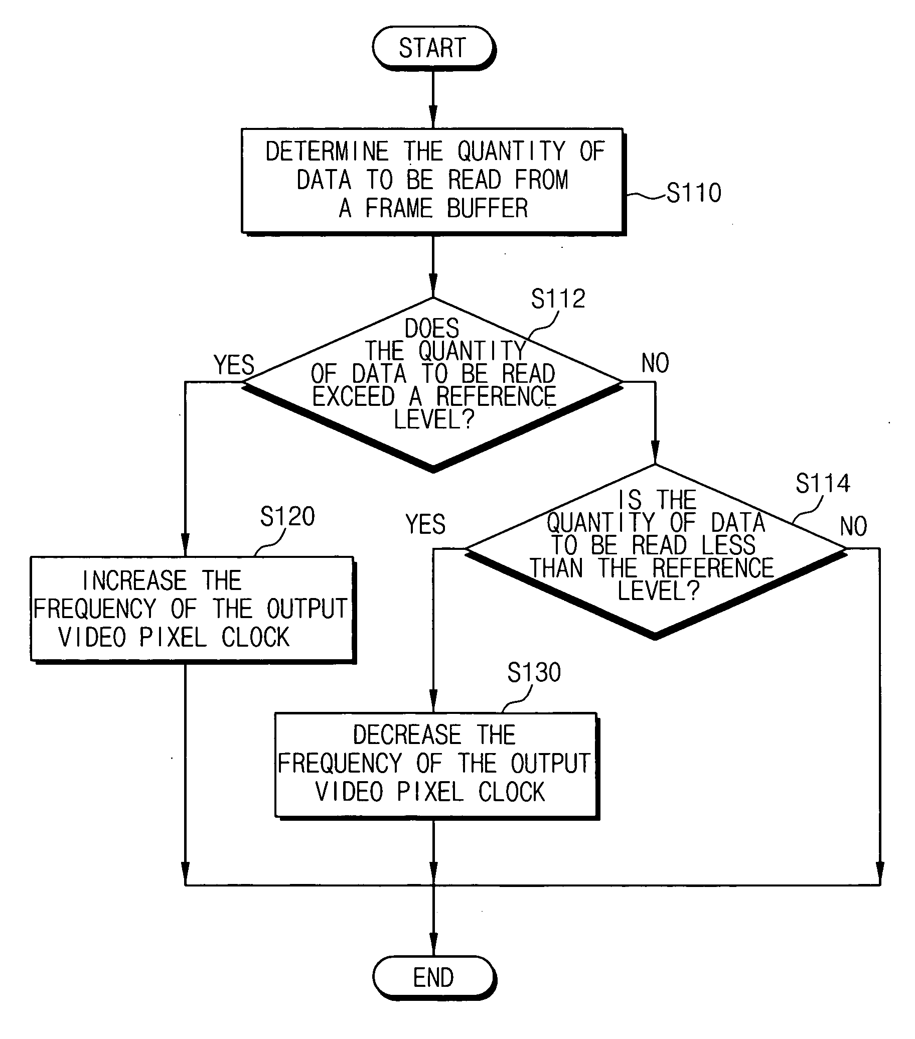
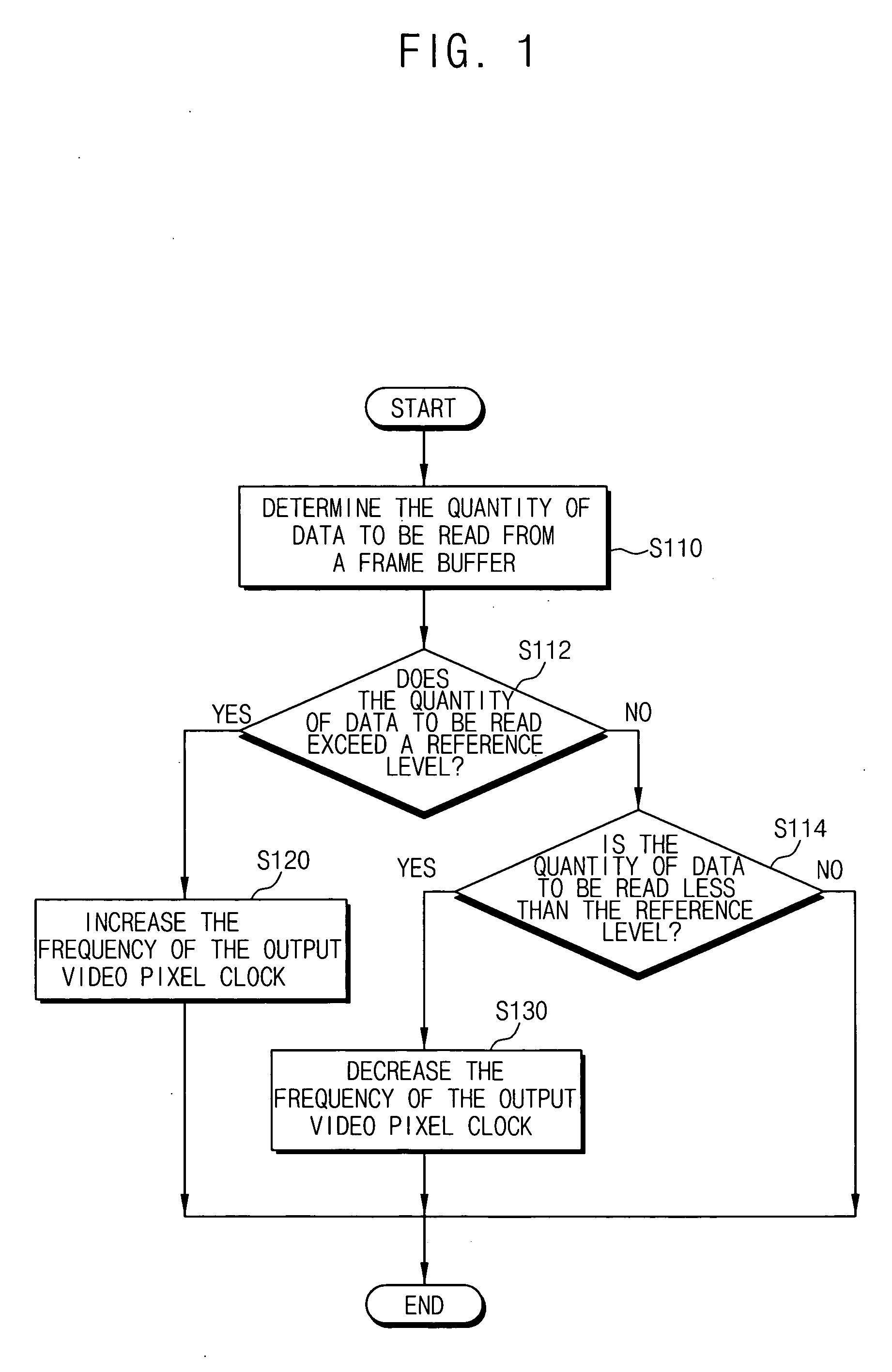
[0025] In one aspect, the modifying of the frequency of the output video pixel clock includes increasing the frequency of the output video pixel clock when the quantity of data read from the frame buffer is greater than a reference level, and decreasing the frequency of the output video pixel clock when the quantity of data read from the frame buffer is less than the reference level.

Problems solved by technology

As the input image signal may be output in various formats having different video pixel clocks, it is difficult to continually generate an output video pixel clock precisely matching an input video pixel clock.
However, implementing the phase-locked loop for producing a precise frequency output that matches the input video clock is difficult, and if implemented, the PLL circuit may have an increased complexity, resulting in an increased size.
Therefore, manufacturing costs and chip size may be increased.
However, according to the above conventional technique, frames are merely repeated or eliminated so that the display quality of images may be degraded.
However, the hardware employed may have increased complexity and access to memory is increased, thereby affecting the bandwidth of a system.
However, circuitry for calculating the phase differences between the input VSYNC and the output VSYNC is needed, and the use of such circuitry and the voltage controlled crystal oscillator may increase the size of the hardware employed.

Method used


Image

  • Method for generating a video pixel clock and apparatus for performing the same
  • Method for generating a video pixel clock and apparatus for performing the same
  • Method for generating a video pixel clock and apparatus for performing the same

Examples


Embodiment Construction

[0041] Hereinafter, the present invention will be explained in detail with reference to the accompanying drawings.

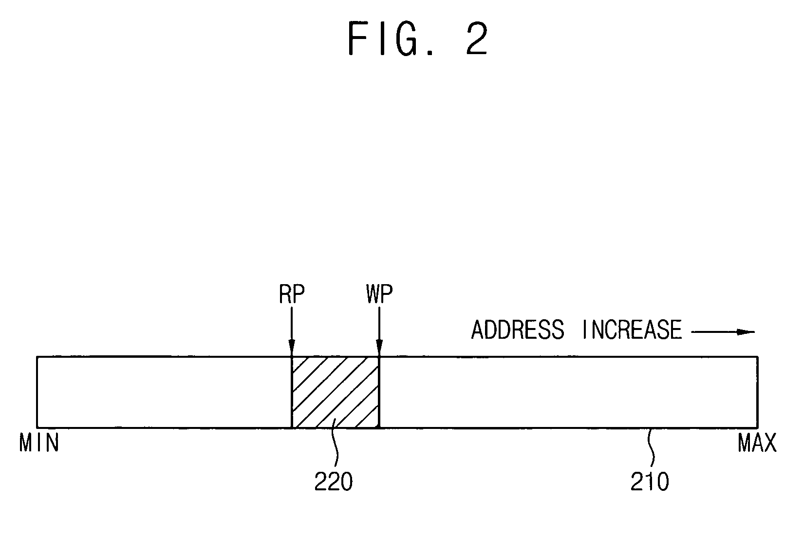
[0042]FIG. 1 is a flowchart illustrating a method of generating a video pixel clock according to an exemplary embodiment of the present invention and FIG. 2 illustrates a status of a frame buffer according to an exemplary embodiment of the present invention.

[0043] Referring to FIG. 1, the quantity of data to be read from a frame buffer is determined S110. The frame buffer is used to store input video data. For example, the frame buffer may be used to store the video data corresponding to three frames.

[0044] The data to be read from the frame buffer is the data that has not been read after the data is written to the frame buffer. The frame buffer may have a read pointer and a write pointer. The write pointer may be increased as the video data is stored in the frame buffer corresponding to the input video pixel clock. The read pointer may be increased as the video data ...


PUM


Abstract

In a method of generating a video pixel clock, a frequency of an output video pixel clock is increased to a first frequency setting when a quantity of data read from a frame buffer storing video data is greater than a reference level. The frequency of the output video pixel clock is decreased to a second frequency setting when the quantity of data read from the frame buffer is less than the reference level. Accordingly, an imbalance between frame rates of input and output image signals may be reduced.

Description

CROSS-REFERENCE TO RELATED APPLICATION [0001] This application claims priority under 35 USC § 119 to Korean Patent Application No. 2005-4516, filed on Jan. 18, 2005, the contents of which are herein incorporated by reference in their entirety. BACKGROUND OF THE INVENTION [0002] 1. Field of the Invention [0003] The present invention relates to a display driver, and more particularly to a method for generating a video pixel clock that is used for a display driver and an apparatus for performing the same. [0004] 2. Description of the Related Art [0005] Generally, a display driver is used to display images on a display device such as a liquid crystal display (LCD), a plasma display panel (PDP), a cathode ray tube (CRT), a digital lighting processing (DLP) projection system, etc., using an input digital signal or an input analog signal. [0006] Because of the widespread adoption of digital image applications such as digital television, the display driver is required to process image signa...

Claims


Application Information

Patent Timeline
Patent Type & Authority Applications(United States)
IPC IPC(8): H04N5/06H03L7/00
CPCG09G5/005G09G5/395H04N5/46
Inventor CHO, SOON-JAE
Owner SAMSUNG ELECTRONICS CO LTD
Learn More