Optical compensator array for dispersive element arrays

a technology dispersive element array, which is applied in the field of optical compensator array for dispersive element array, can solve the problems of polarization sensitivity or the need for closed-loop feedback, and achieve the effect of reducing the temperature sensitivity of the system

Inactive Publication Date: 2006-07-20
JDS UNIPHASE CORP
View PDF19 Cites 59 Cited by
  • Summary
  • Abstract
  • Description
  • Claims
  • Application Information

AI Technical Summary

Benefits of technology

[0018] In some embodiments, the optical wedges have coefficients of thermal expansion selected to reduce temperature sensitivity of a system within which the array of wedges is i...

Problems solved by technology

Depending upon the fabrication techniques employed to make the WDE array, there may be errors/imperfections in fabrication (for example due to gradient of index of refraction and process non-uniformity across wafer) that may introduce a wavelength shift that may be as large as 300 pm across an array ...

Method used


Image

  • Optical compensator array for dispersive element arrays
  • Optical compensator array for dispersive element arrays
  • Optical compensator array for dispersive element arrays

Examples


Embodiment Construction

[0058] By way of introduction, FIG. 11 is a plot of the optical performance of a particular example implementation of a WSS employing a WDE array showing the performance without any WDE array compensation in “before” curve 30. It can be seen that the “before” curve 30 shows a high insertion loss and high insertion loss non-uniformity across the channels.

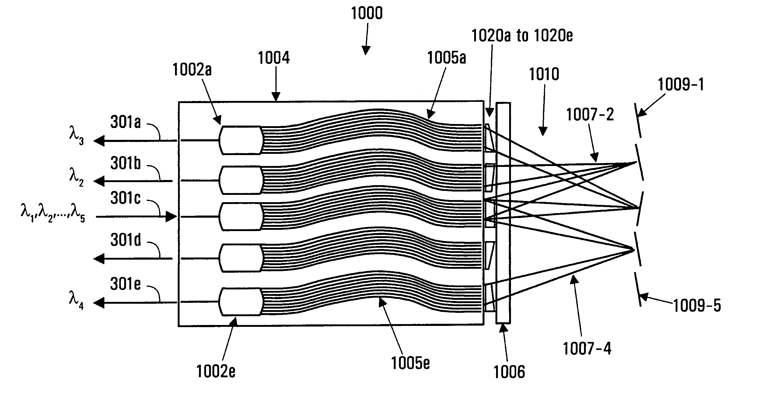
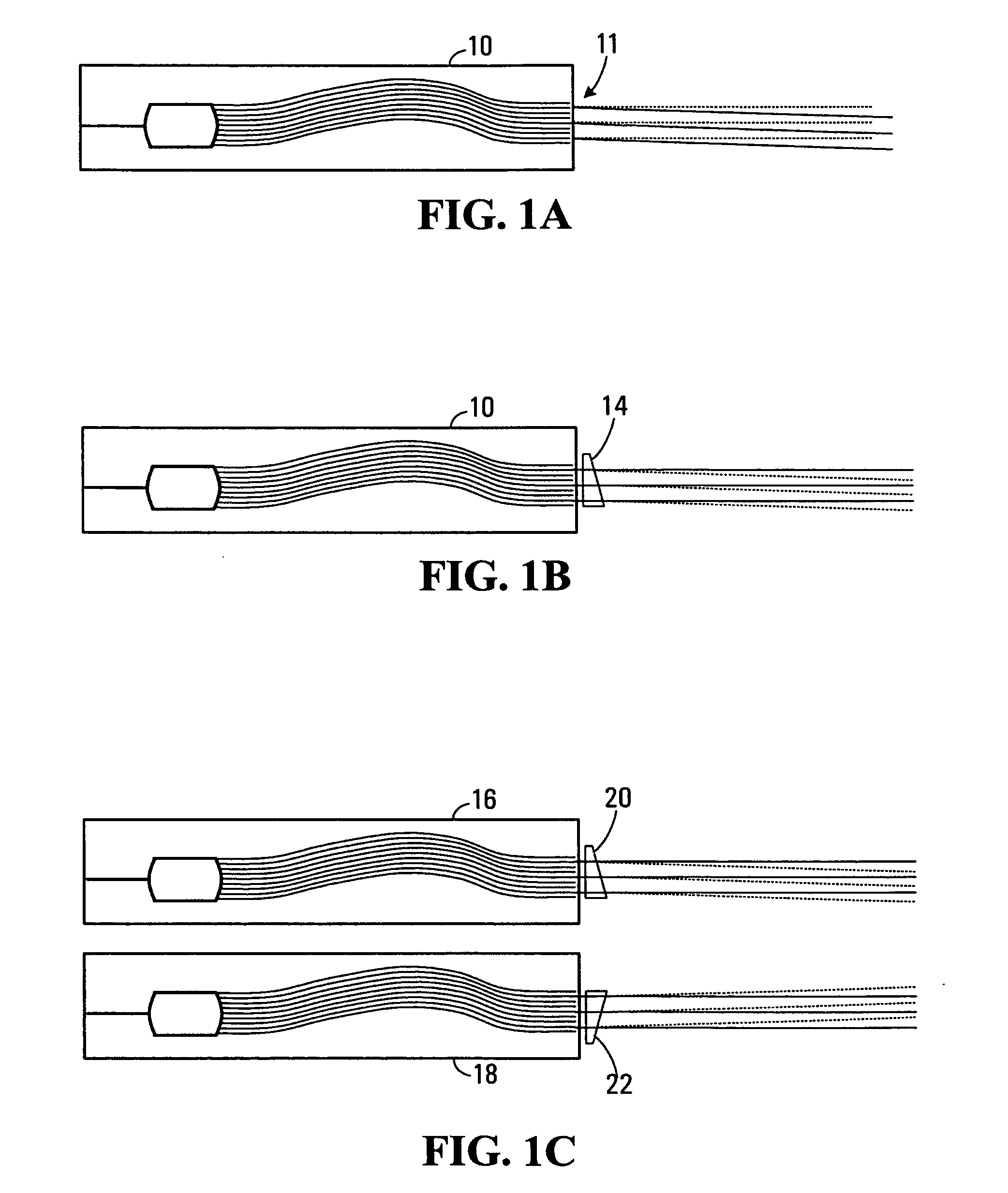
[0059] Regardless of the way an array of dispersive elements is put together (on the same substrate for a WG element, on a stack of WG, glued to a plate or other mounting mechanism), there is a need to precisely align each dispersive arrangement with respect to the others if they are to work together well. The alignment tolerance on those parts can be particularly tight, making an optomechanical mount prohibitively expensive or requiring that the array be fabricated as one monolithic assembly with very high precision.

[0060] Embodiments of the invention provide various techniques for compensating a WDE array and thereby relax alignm...


PUM


Abstract

An array of dispersive arrangements, for example an array of waveguide dispersive elements, is compensated with a set of optical compensators such as wedges or pairs of cylindrical lenses. The optical compensators are selected to achieve a pre-defined dispersion profile across the array of waveguide dispersive elements. The optical compensators can make corrections for fabrication errors or other errors in an optical system that includes the array of waveguide dispersive elements. A particular application is found in waveguide selective switches.

Description

RELATED APPLICATIONS [0001] This application is a continuation-in-part of U.S. Ser. No. 10 / 493,107, filed May 20, 2003 and claims the benefit of U.S. Provisional Application No. 60 / 381,364 filed May 20, 2002, both of which are hereby incorporated by reference in their entirety.BACKGROUND OF THE INVENTION [0002] The wavelength selective switch (WSS) technology taught in Applicant's above-referenced pending U.S. patent application Ser. No. 10 / 493,107 uses an array of waveguide-based dispersive elements (WDE) to demultiplex and multiplex DWDM signals to be processed by a MEMS element. [0003] If made to satisfy defined tolerances, the WDE will all be sufficiently aligned in terms of central wavelength and the optical system will perform with satisfactory optical performance. [0004] Depending upon the fabrication techniques employed to make the WDE array, there may be errors / imperfections in fabrication (for example due to gradient of index of refraction and process non-uniformity across...

Claims


Application Information

Patent Timeline
IPC IPC(8): G02B6/34
CPCG02B6/12011G02B6/12019G02B6/12023G02B6/1203G02B6/29394G02B6/3512G02B6/356
Inventor HNATIW, ALANDUCELLIER, THOMASRANALLI, ELISEO ROMOLOTOUAHRI, DRISS
Owner JDS UNIPHASE CORP
Why Eureka
Try Eureka