Device and method for sterilization

a technology of sterilization device and sterilization method, which is applied in the field of sterilization device and method, can solve the problems of recontamination of sterilized packages after sterilization, risk of recontamination of sterilized packages outside the device, and irradiation with electrons create unwanted x-rays, etc., and achieves simple and fast displacement of packages, facilitate shielding, and facilitate the effect of displacing

Inactive Publication Date: 2006-07-20
TETRA LAVAL HLDG & FINANCE SA
View PDF2 Cites 52 Cited by
  • Summary
  • Abstract
  • Description
  • Claims
  • Application Information

AI Technical Summary

Benefits of technology

[0011] Thus, the invention comprises a shielding formed so that it is possible to pass partly formed packages between the outside of the shielding and a space inside the shielding, and still minimise the risk of X-rays being able to find their way out of the shielding, without first having their energy reduced to an acceptable limiting value. The limiting value can for example be settled by governmental regulations or market acceptance.
[0045] In another preferred embodiment the method comprises the steps of: providing the inner chamber with a gaseous fluid outlet, providing the outer chamber in connection with an outer housing via a package opening, the outer housing at least partly surrounding a package conveyor and being provided with gaseous fluid supplies, at least one of which is being located in a portion of the outer housing that is being arranged from the package opening in a direction being the direction of travel of the package conveyor, and at least one of which being located in a portion of the outer housing that is being arranged from the package opening in a direction opposite the direction of travel of the package conveyor, creating a flow of the gaseous fluid towards the package opening in the housing, through the opening and into the outer chamber, through the carrier unit, and through the inner chamber to the gaseous fluid outlet. By providing such a flow of gaseous fluid through the device a satisfactory level of sterilization can be maintained for products not being that sensitive, for example juices, and products which are to be distributed in chilled environment. Further, as previously mentioned, ozone that is formed during irradiation with electrons can be effectively and reliably discharged from the chambers by the same flow of gaseous fluid. The risk of leakage of ozone to the outside of the device and the outer housing is thereby minimised.

Problems solved by technology

However, irradiation with electrons creates unwanted X-rays.
So far it has been a problem to obtain acceptable radiation levels outside an irradiation device of reasonable size where RTF packages can pass into and out from in short time.
Somewhat similar problems arise with sterilization using ultraviolet radiation or chemical sterilization using for instance hydrogen peroxide in gas phase.
Unfortunately, bacteria and other spoilage organisms may enter through the openings and also through interconnections between different portions of the device and the surrounding equipment.
If these bacteria and spoilage organisms are left in the device they may recontaminate the packages after they have been sterilized.
Thus, there is also a risk of recontamination of sterilized packages outside the device.

Method used


Image

  • Device and method for sterilization
  • Device and method for sterilization
  • Device and method for sterilization

Examples


first embodiment

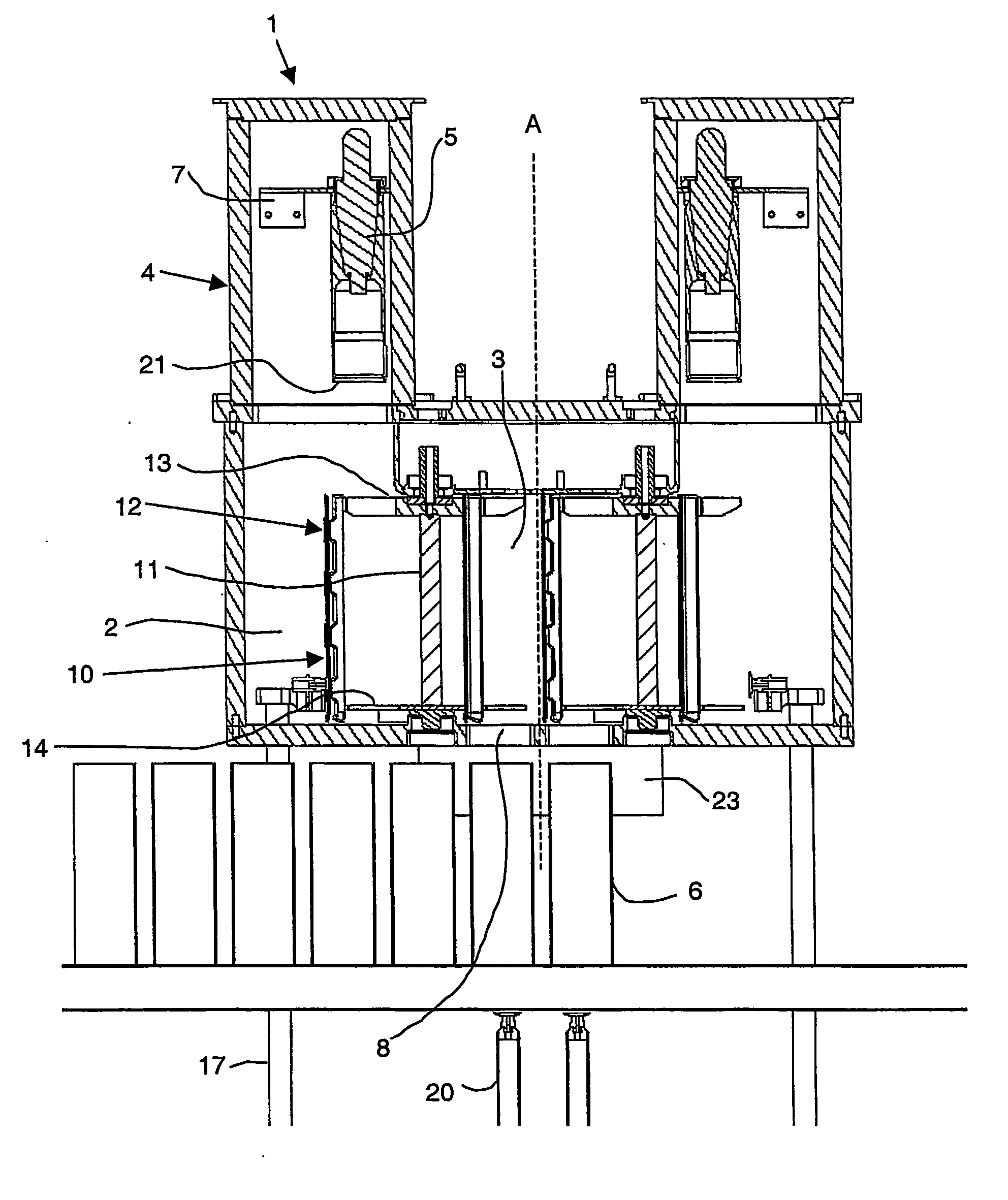
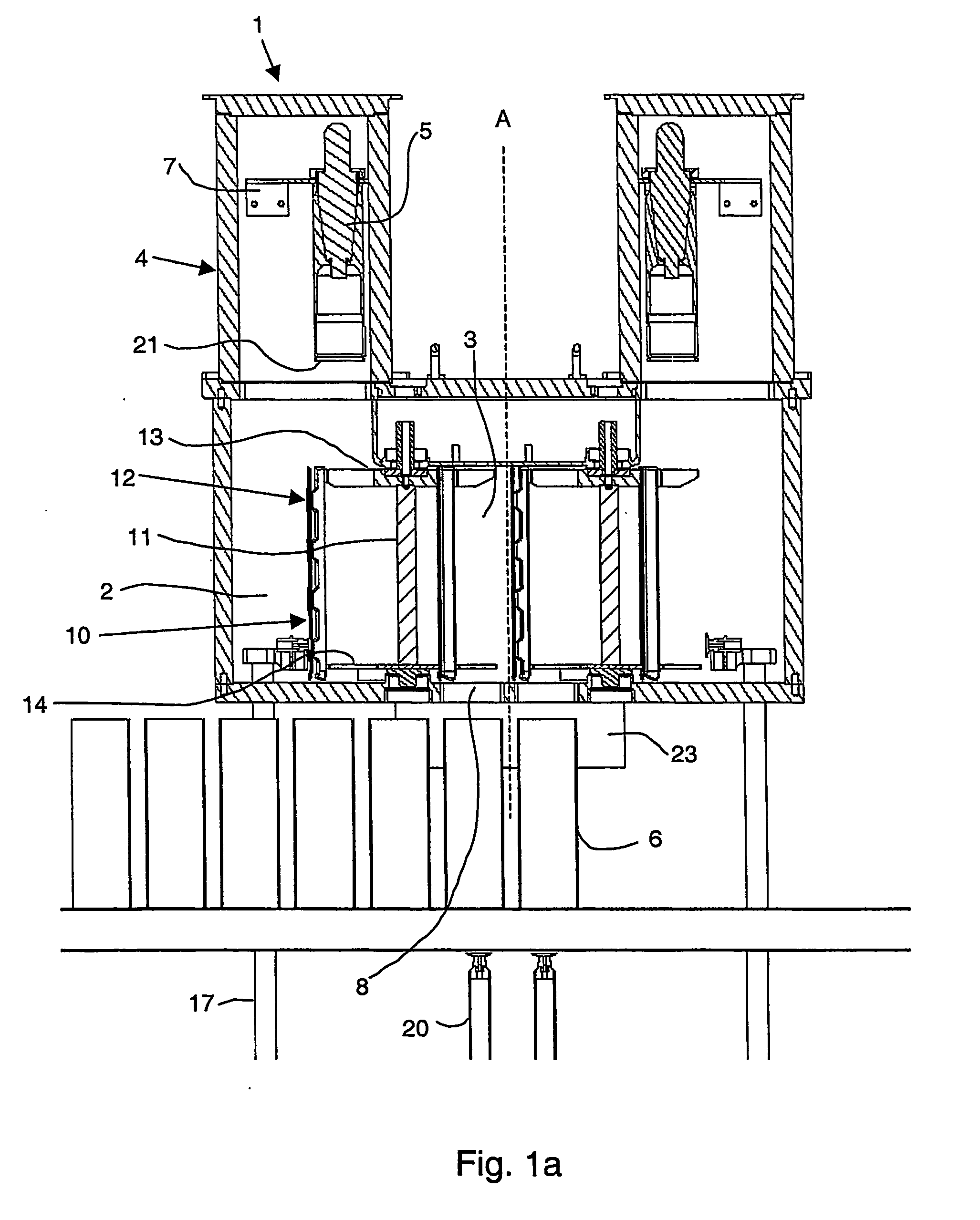
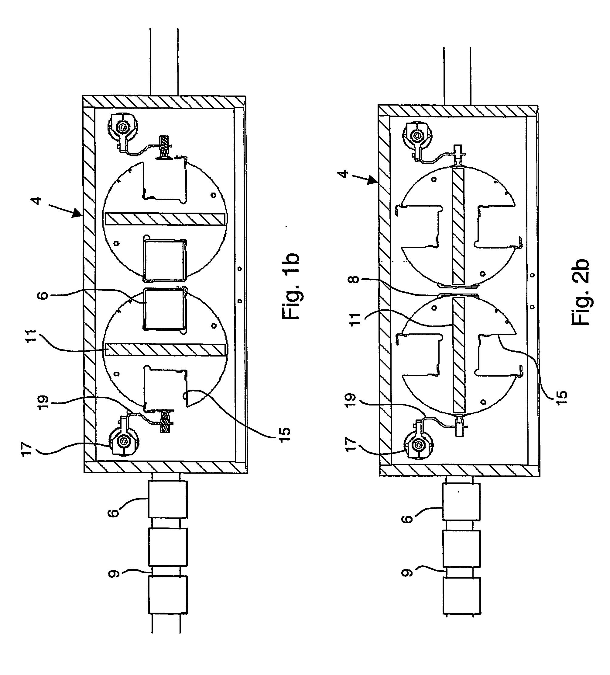
[0108] In the first embodiment, shown in FIG. 6, this flow of gaseous fluid is created from the inner chamber 2, through the carrier unit 10, through the outer chamber 3, through the package opening 8 in the housing 4 to an outer housing 24, and through at least a portion of said outer housing 24 in a direction towards a gaseous fluid outlet 26.

[0109] The outer housing 24 is used to control the flow of air and comprises a U-formed member in connection with the housing 4. The U-form is adapted to form a tunnel extending along a portion of the conveyor 9. The middle portion of the U is fastened to the bottom of the housing 4 and the leg portions of the U are directed towards the conveyor 9 so that one leg is arranged on each side of the conveyor 9. Thus, the package conveyor 9 will act as a bottom of the tunnel and the middle portion of the U-form will act as a roof. The U-formed member 24 is made of thin sheet metal. To the left in the figure there is a package infeed 24a in the oute...

second embodiment

[0123] The air system further comprises at least one suction pipe 33 located in the upper portion of the outer housing 24, the pipe 33 being directed down towards the openings of the packages 6 to be able to ventilate the air in the packages 6 before they exit the outer housing 24. The suction pipe 33 is connected to the ozone filter unit 31 so that the air that is ventilated out from the packages 6 is filtered and returned to the system.

[0124] The device 1 also comprises a cooling water circuit for cooling the emitters, but this circuit will not be described.

[0125] Moreover, the invention refers to a method for sterilizing at least partly formed packages 6 in a packaging machine. In the method an inner chamber 2 and an outer chamber 3 are provided and a sterilizing unit 5 is arranged in the inner chamber 2 for sterilizing at least the inside of at least one package 6. Further, a carrier unit 10 is provided comprising at least one separating member 11 and at least one package carr...


PUM

PropertyMeasurementUnit
thicknessaaaaaaaaaa
rotationaaaaaaaaaa
temperatureaaaaaaaaaa

Abstract

The invention refers to a device (1) and method for sterilizing partly formed packages (6) in a packaging machine. The device (1) comprises an inner chamber (2) and an outer chamber (3), the inner chamber (2) being provided with a sterilization unit (5). Further, it comprises a carrier unit (10), comprising a separating member (11) and a package carrying member (12), which is being adapted to rotate between a first position in which the package carrying member (12) is located in the outer chamber (3), and in which the separating member (11) separates the inner chamber (2) from the outer chamber (3), and a second position in which the carrier unit (10) has rotated a package (6) into the inner chamber (2) and in which the separating member (11) separates the inner chamber (2) from the outer chamber (3).

Description

THE FIELD OF INVENTION [0001] The present invention refers to a device and a method for sterilizing at least partly formed packages in a packaging machine. TECHNICAL BACKGROUND [0002] Within the food packaging industry it has for a long time been used packages formed from blanks of packaging material, the material being comprised of different layers of paper or board, liquid barriers of for example polymers and gas barriers of for example thin films of aluminium. The blanks are preformed from a material web, which is provided with a pattern of crease lines facilitating forming and folding of packages. The web is cut into pieces, each piece having a size and shape for making one package. After cutting, each piece is folded into a flat tube-formed blank having its longitudinal edges overlapping each other. Next, the longitudinal edges are sealed by any appropriate, conventional sealing technology such as for example heat sealing. The result is a flat tube-formed blank. Forming a blank...

Claims


Application Information

Patent Timeline
Patent Type & Authority Applications(United States)
IPC IPC(8): A61L2/08B65B55/02B65B55/08
CPCB65B55/027B65B55/08A61L2/08A61L2202/122
Inventor NASLUND, LARS AKEHERMODSSON, GORANMARTENSSON, LARSDEIVASIGAMANI, ARUNANDERSSON, PAUL
Owner TETRA LAVAL HLDG & FINANCE SA
Why Eureka
Try Eureka