Disposable laparoscopic instrument

a laparoscopic instrument and jaw member technology, applied in the field of surgical instruments, can solve the problems of difficult to achieve adequate sterilization for reuse, difficult to connect the shaft and the handle assembly, and the mechanics involved in the instrument have not changed much, so as to improve the ejecting of parts, maintain stability, and reduce rotating friction

Inactive Publication Date: 2006-07-20
APPL MEDICAL RESOURCES CORP
View PDF64 Cites 174 Cited by
  • Summary
  • Abstract
  • Description
  • Claims
  • Application Information

AI Technical Summary

Benefits of technology

[0008] In another aspect, the knob has internal key couplings for rotating the outer tube of the shaft assembly. Specifically, the knob may further include a hub, an alignment hole, and a retaining pin or other similar retention means for coupling the knob to the handle assembly to allow 360° rotation. The handle assembly may include a circumferential groove where a retaining pin of the knob is to be placed, inserted or extended to allow rotation. The knob may further include a spring washer between the distal end of the handle assembly and the proximal end of the hub to take up the linear play due to tolerance variations. The hub may be formed of a plastic material and may be overmolded onto the outer tube to provide secure coupling. The hub may also be coupled to the outer tube with an adhesive or other coupling means. The rotatable knob may also have a plurality of ribs on its inside diameter, providing a thin-walled knob while maintaining stability and reducing rota

Problems solved by technology

Unfortunately, the complexity of the mechanics involved in these instruments has not changed much and has made it difficult to achieve adequate sterilization for reuse.
A drawback of this apparatus is the difficulty of connecting together the shaft and the handle assembl

Method used


Image

  • Disposable laparoscopic instrument
  • Disposable laparoscopic instrument
  • Disposable laparoscopic instrument

Examples


Embodiment Construction

[0027] The invention and its various embodiments can now be better understood with the following detailed description wherein illustrated embodiments are described. It is to be expressly understood that the illustrated embodiments are set forth as examples and not by way of limitations on the invention.

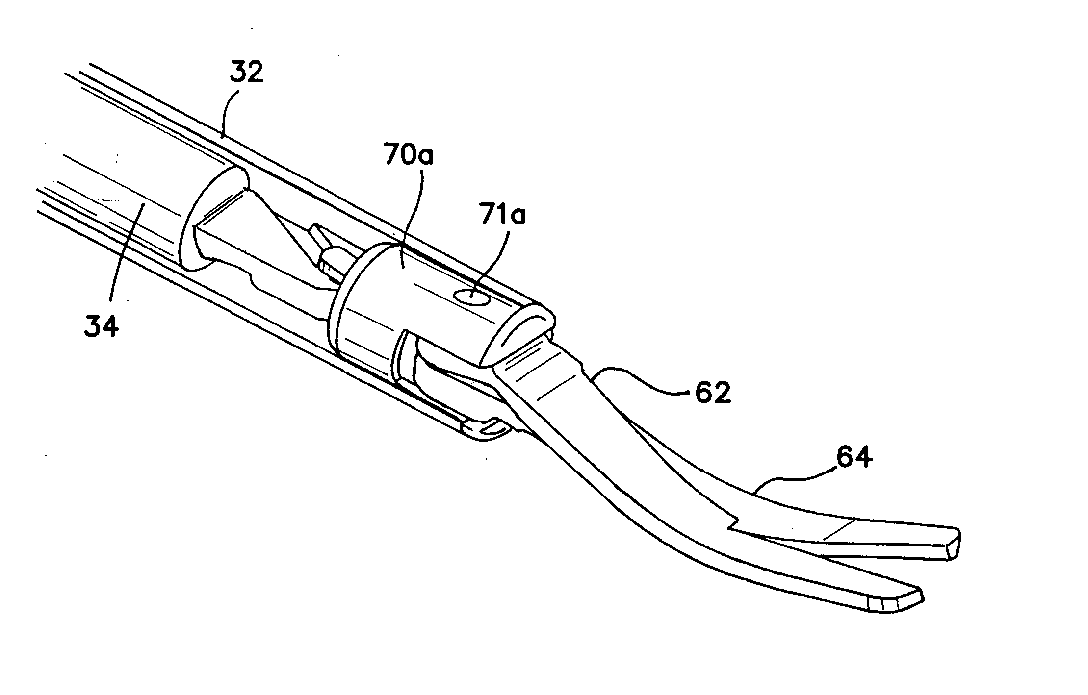
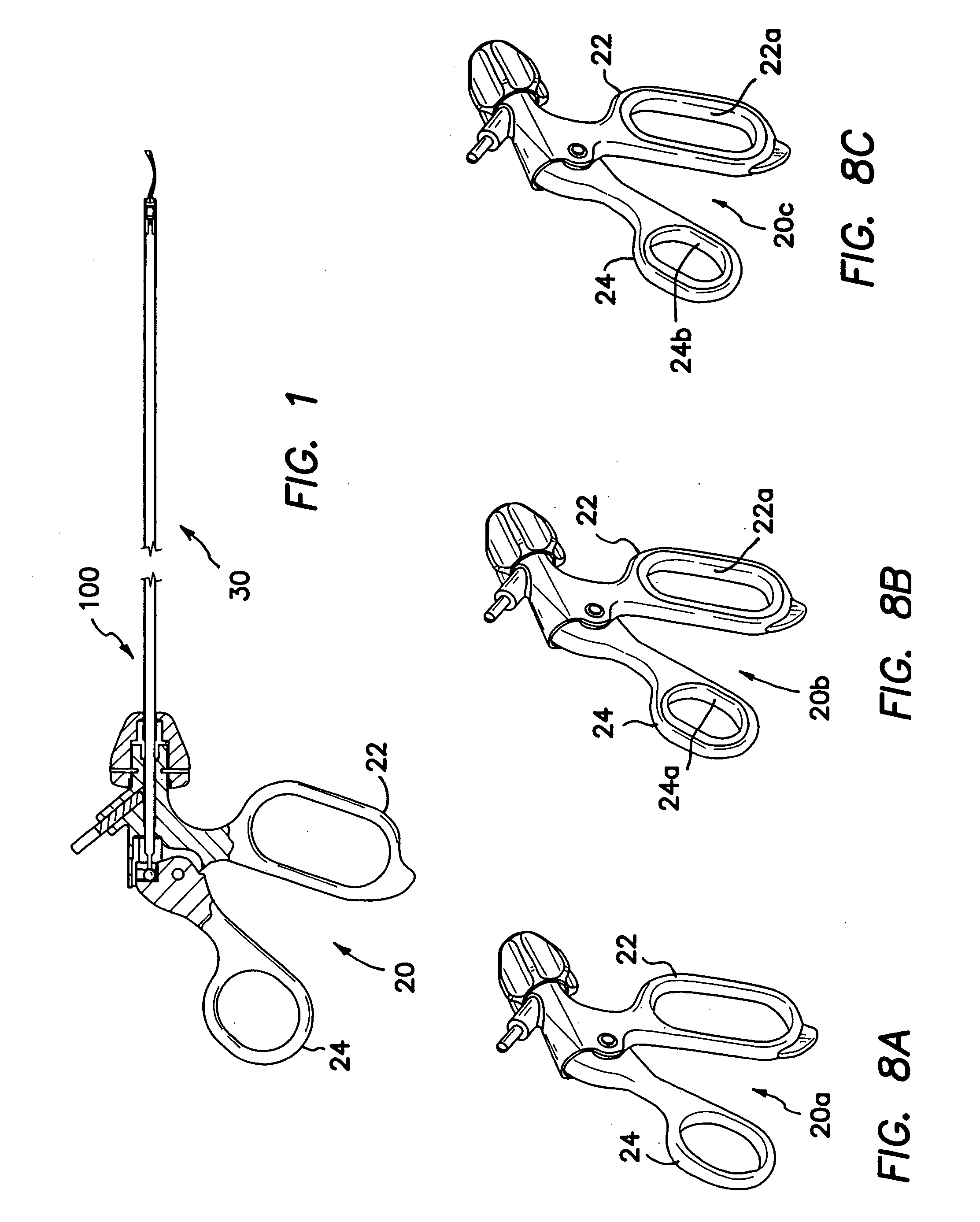
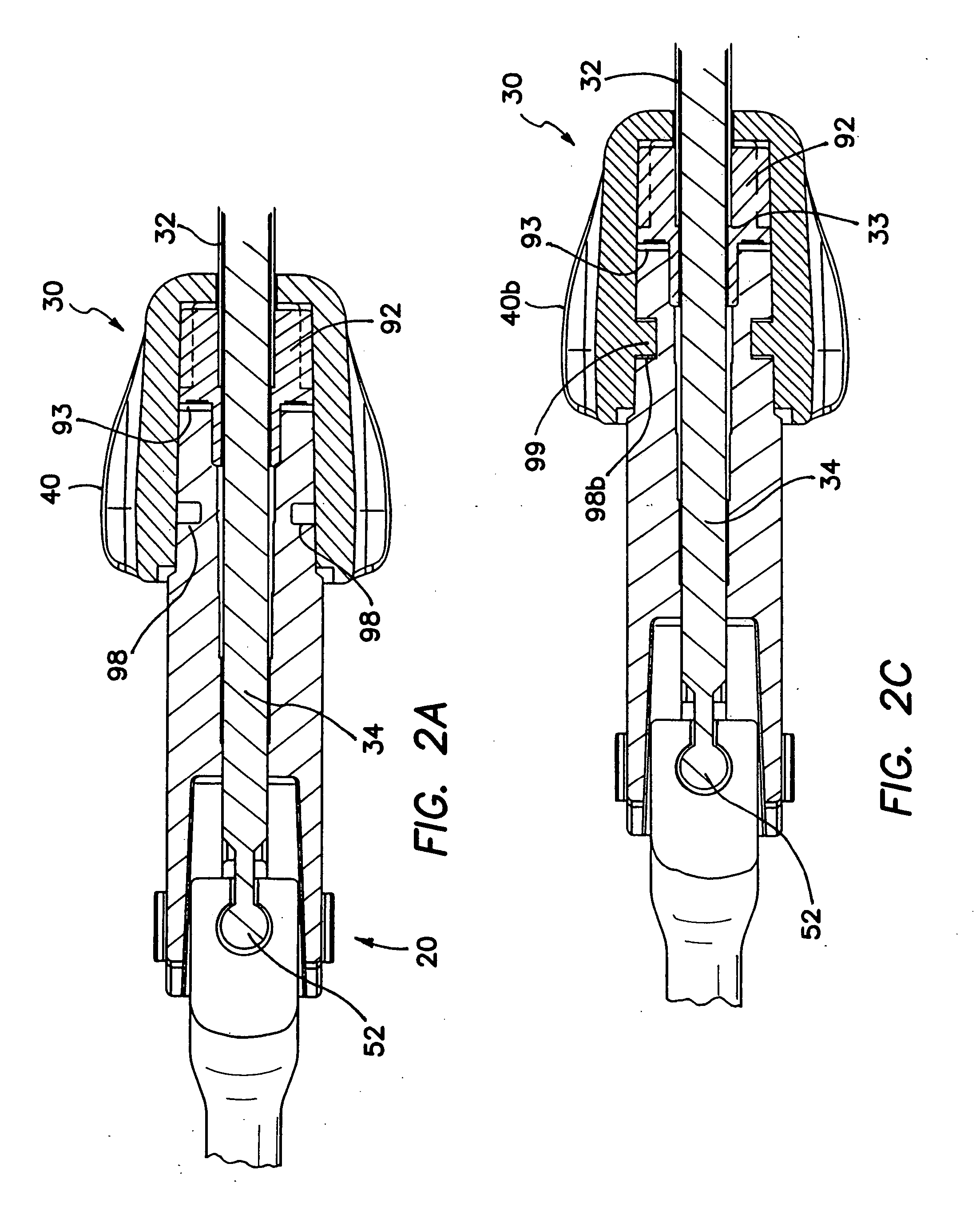
[0028] A first embodiment of a surgical instrument is illustrated in FIG. 1 and designated by the reference numeral 100. The surgical apparatus 100 includes a handle assembly 20 and a shaft assembly 30. The handle assembly 20 further includes a fixed handle 22 and a pivoting handle 24. Referring to FIGS. 2A and 2B, there are shown cross-sectional views of the connections between the handle assembly 20 and the shaft assembly 30. In particular, the shaft assembly 30 extends distally from the handle assembly 20 and further includes an outer tube 32 and an inner actuation rod 34 that slides coaxially within the outer tube 32. The shaft assembly 30 may be a 5 mm diameter shaft having an a...


PUM


Abstract

The invention is directed to a surgical instrument including a handle assembly and a shaft assembly. The handle assembly further includes a fixed handle and a pivoting handle. The shaft assembly extends from the handle assembly and further includes an outer tube and an inner actuation rod that slides coaxially with the outer tube. The shaft assembly includes a rotatable knob to provide 360° rotation. The actuation rod has a proximal end and a distal end; the proximal end has a ball end that couples with the pivoting handle to form a rotatable ball-and-socket joint. The outer tube is formed of plastic and fits over the actuation rod to function as an electrical insulator.

Description

[0001] This application fully incorporates by reference and claims priority to: provisional application, Ser. No. 60 / 725,234, filed by Applicants on Oct. 11, 2005, entitled “Disposable Laparoscopic Instrument;” provisional application, Ser. No. 60 / 665,069, filed by Applicants on Mar. 24, 2005, entitled “Disposable Laparoscopic Instrument;” and provisional application, Ser. No. 60 / 645,319, filed by Applicants on Jan. 19, 2005, entitled “Disposable Laparoscopic Instrument.”BACKGROUND OF THE INVENTION [0002] This invention generally relates to surgical instruments and, more specifically, to a disposable laparoscopic instrument having jaw members that pivot in response to the opening and closing of a handle member, where movement of the handles is translated through a shaft member to open and close the jaw members and to facilitate access to distant operative sites. [0003] It is often desirable to cut tissue, occlude vessels or perform some other surgical procedure at a distant operativ...

Claims


Application Information

Patent Timeline
IPC IPC(8): A61B17/32A61B17/28
CPCA61B10/06A61B17/1608A61B17/29A61B17/3201A61B18/1445A61B2017/0023A61B2017/2902A61B2017/292A61B2017/2929A61B2017/2934A61B2017/2936A61B2017/294A61B2017/2945A61B2018/1432
Inventor GADBERRY, DONALD L.JOHNSON, GARY M.ALBRECHT, JEREMY J.OKIHISA, DAVIDHILAL, SAID S.STROKOSZ, ARKADIUSZ A.
Owner APPL MEDICAL RESOURCES CORP
Why Eureka
Try Eureka