
Uv led based water purification module for intermittantly operable flow-through hydration systems

a technology of intermittant operation and water purification module, which is applied in the direction of machine/engine, process and machine control, and material analysis using wave/particle radiation. it can solve the problems of complex circuitry, high cost and fragile ccfl uv lamp assemblies, and inability to adapt well to wearable hydration systems. it can eliminate batteries and the like

Active Publication Date: 2006-07-27
KATADYN NORTH AMERICA INC
View PDF13 Cites 49 Cited by
  • Summary
  • Abstract
  • Description
  • Claims
  • Application Information

AI Technical Summary

Benefits of technology

[0007] The UV LEDs are DC devices, and thus, require simpler, lower cost drive and control circuitry, than is required to operate CCFL lamps. Further, the UV LEDs are solid state devices and are thus less fragile than the CCFL lamps. Accordingly, the UV LEDs are well suited for intermittently operated wearable or portable flow-through hydration devices, such as wearable bladders, user-carried or worn sports water bottles, and so forth.
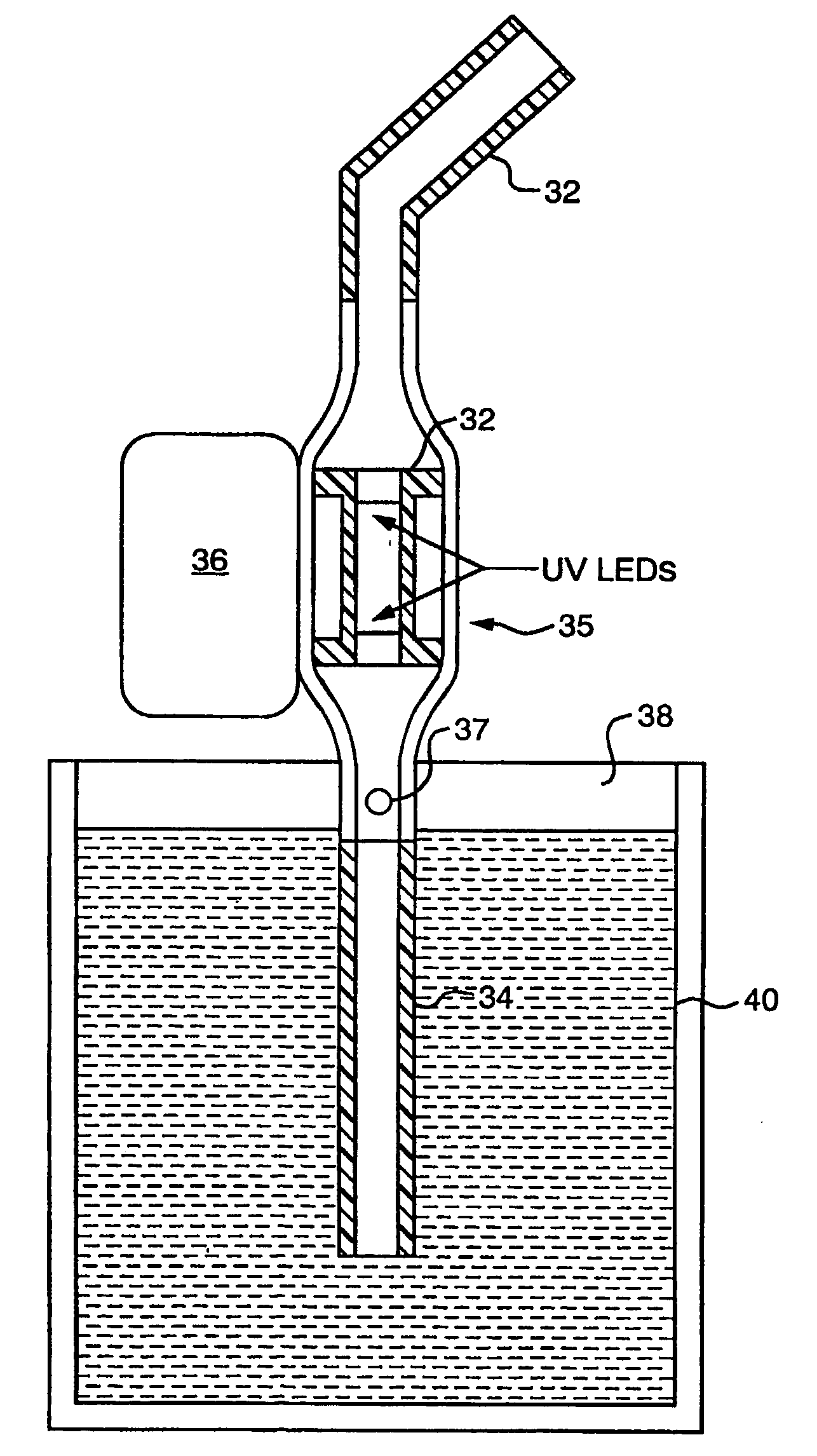
[0009] The purification module and associated water flow sensor may instead be positioned in a drinking straw, and thus, be used to purify water flowing through the straw from any type of water bottle, canteen and so forth, carried by the user. The purification module may additionally include a filter that removes sediment from the water. Alternatively, the purification module may be included in the tubing of a portable water filtering system, such as a pump system used by campers. The filter in such a system may then be relatively coarse, since the filter needs only to trap sediment and not microbes, which are destroyed by the purification module. Further, such a filtering system would not require use of chemicals. In addition, the pump action may be harnessed to power the UV LEDs, and batteries and the like may thus be eliminated.

Problems solved by technology

However, the CCLF lamps are not well suited for wearable hydration systems.
The lamps and their thermally insulating sleeves must be made from high quality, optical grade quartz, and thus, the CCFL UV lamp assemblies tend to be both costly and fragile.
In addition, the CCFL UV lamps require high voltage AC power, and the circuitry needed to deliver this power is complex and relatively expensive, particularly if the input is from a DC source such as a battery.
During this “ramp-up” period, any water flowing past a CCFL UV lamp will not have predictable or uniform UV exposure.
As a result, the efficacy of the treatment of water in such a flow-through system, from a micro-biological standpoint, becomes unpredictable and unreliable.
Achieving this steady-state output may take up to several minutes.
In a wearable flow-through hydration system or other intermittently operated on-demand flow-through systems, water consumption is not only intermittent but sudden and unpredictable.
In the first, the lamp must be kept on all the time and consumption of limited battery power quickly becomes a problem.
In the second, the lamp must be turned on minutes before taking each drink and there is an obvious inconvenience.

Method used


Image

  • Uv led based water purification module for intermittantly operable flow-through hydration systems
  • Uv led based water purification module for intermittantly operable flow-through hydration systems
  • Uv led based water purification module for intermittantly operable flow-through hydration systems

Examples


Embodiment Construction

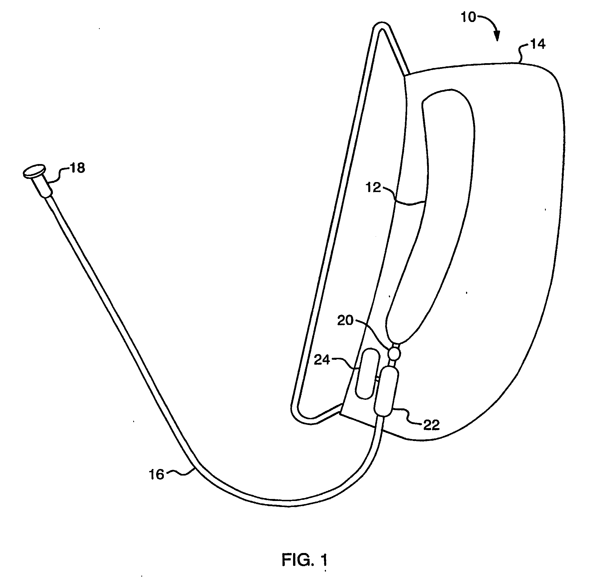
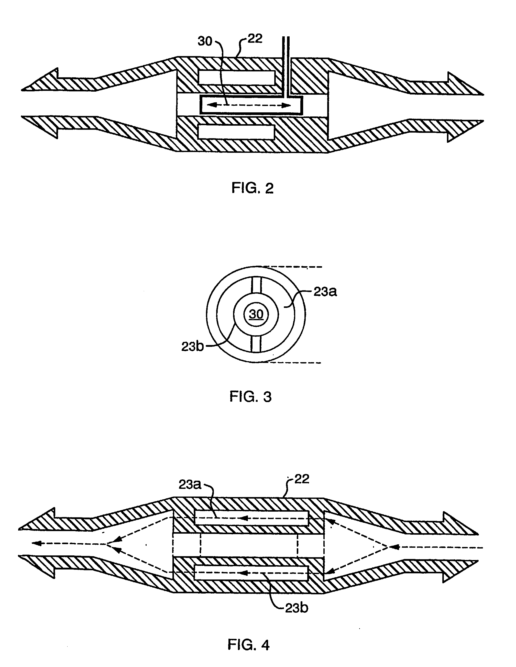
[0018] As shown in FIG. 1, a wearable flow-through hydration system 10 includes a bladder 12 that is contained in a backpack 14. The bladder supplies hydrating fluids, such as water, to a user through a tube 16 and mouthpiece 18. The tube includes a purification module 22 that ensures that the water is sufficiently irradiated by ultraviolet (“UV”) light in the germicidal range. As the water flows through the module 22, the UV radiation destroys the DNA of the microbes present in the water, thereby preventing microbial reproduction, and therefore, infection. The purification module 22 is discussed in more detail below with reference to FIGS. 2-4

[0019] When a user requires water from the bladder 12, the water is drawn out of the bladder and flows past a water flow sensor 20. When the water flow sensor senses the flow, the sensor switches on the purification module 22. A power supply 24 supplies between 6 and 9 volts DC power to the purification module, and as discussed in more detail ...


PUM

PropertyMeasurementUnit
Surface energyaaaaaaaaaa
Poweraaaaaaaaaa
Flow rateaaaaaaaaaa

Abstract

A wearable or portable intermittently operable hydration system (10) includes a purification module (22) that contains one or more solid state UW devices that are positioned in the path of hydrating fluid, or water, flow through the hydration system to a mouthpiece (18) or other orifice. The purification module (22) provides a path for the fluid past one or more solid state LW devices, such as LW LEDs, that produce LW radiation in a germicidal range. When the fluid is flowing past the UV LEDs, the LEDs are turned on to provide sufficient UW radiation to purify the water. The UW LEDs are instant on devices with essentially no ramp-up required, and a sensor (20) or other signaling means in the flow path controls the turning on of the UV LEDs whenever the user initiates the fluid flow. The fluid flow path may run from a bladder (12) in a backpack (19) worn by the user, a sports bottle worn by or carried by the user or may be through a water filtration system that a user operates via a pump. The power for the purification module may come from batteries, solar cells, fuel cells, power converted from pumping or winding action or any combination thereof. Further, UV LEDs may be included in the walls of the container as additional or alternative sources of UV radiation. The UV LEDs in the walls of the container may then be turned on when sufficient energy is available, as a precaution against, for example, a change in environmental conditions.

Description

FIELD OF THE INVENTION [0001] The inventive system described herein uses ultraviolet (“UV”) light emitting diode (LED) technology to disinfect drinking water in intermittently operated flow-through hydration systems, such as wearable bladder bags. In such systems, water generally flows intermittently and on-demand from a bladder bag, or other “reservoir,” through a tube and out into the user's mouth or, alternately, a drinking vessel. BACKGROUND OF THE INVENTION [0002] Currently, most UV water treatment systems use low pressure cold cathode fluorescent (CCFL) mercury vapor lamps with a primary radiative emission of 254 nanometers (2,537 angstroms). This wavelength, which falls within the short wave UV-C band, is highly germicidal. [0003] The CCFL UV lamps can be very effective in batch UV water purification systems, such as the system described in U.S. Pat. Nos. 5,900,212 and 6,110,424. However, the CCLF lamps are not well suited for wearable hydration systems. The lamps and their t...

Claims


Application Information

Patent Timeline
IPC IPC(8): C02F1/78A45F3/20C02F1/32
CPCA45F3/20A45F2003/163C02F1/003C02F1/325C02F2201/009C02F2201/3222C02F2209/40C02F2307/02Y02W10/37Y02A20/212
Inventor MAIDEN, MILES
Owner KATADYN NORTH AMERICA INC
Learn More