Two-circuit grip heater

Inactive Publication Date: 2006-07-27
HOLLANDER JAMES M
View PDF7 Cites 20 Cited by
  • Summary
  • Abstract
  • Description
  • Claims
  • Application Information

AI Technical Summary

Benefits of technology

[0014] To simplify the circuitry and to provide a grip which is suitable to retrofit many of the conventional circuits in service, it is preferred for the heating elements to be connected together at their unswitched ends to provide a common ground. As discussed above, if such is done, it is

Problems solved by technology

Grip heaters are employed to heat the hand grips of motorcycles, snowmobiles, and similar equipment which are operated in cold weather but which require sufficient dexterity on the part of the user to make the wearing of bulky mittens or gloves impractical.
The printed circuits maintain reasonable grip thickness since the conductors are thin and flat; however, these conductors tend to break down at one or more locations along the conduction during use.
These breakdowns may result from damage to the printed circuits due, in part, to mechanical straining of the circuit by the user applying force or torque to the grip to maneuver the device to which it is attached.
The mechanical strains introduce irregularities which in turn causes the temperature to spike, causing local deterioration of the circuit and ultimately failure; this limits the useful life of such devices.
Two additional problems that have been found in printed circuit grip heaters are delamination and heat loss.
Over time, the circuit substrate delaminates from the underlying structure, apparently due to thermal degradation of the laminating adhesive, again reducing the life of

Method used


Image

  • Two-circuit grip heater
  • Two-circuit grip heater
  • Two-circuit grip heater

Examples


Embodiment Construction

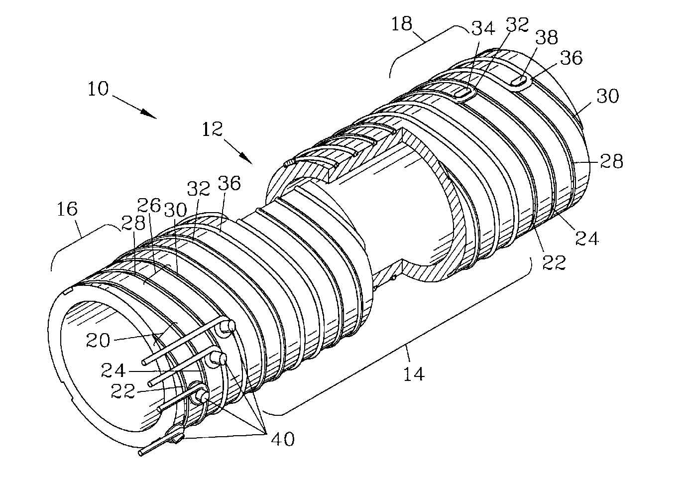
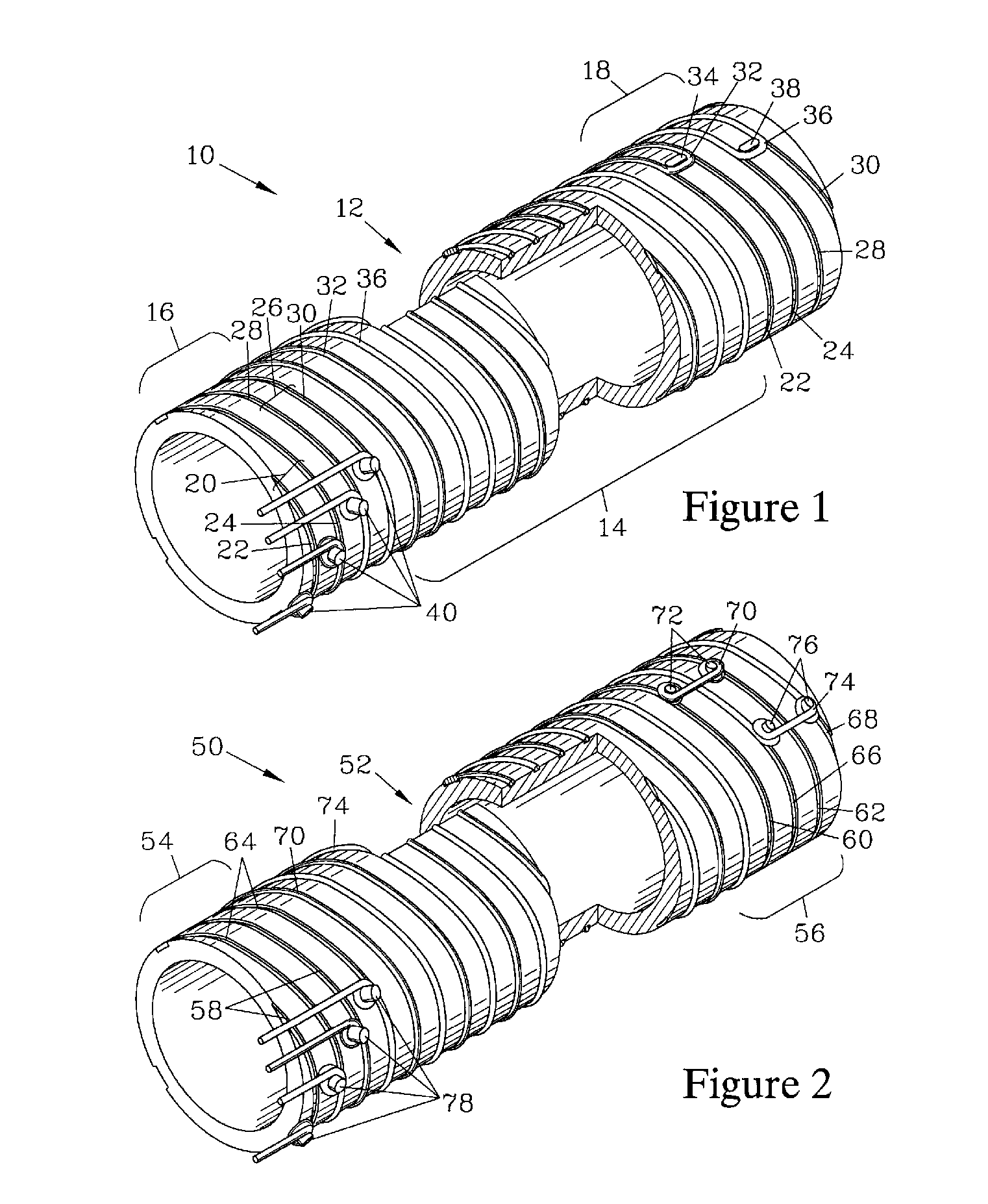
[0025]FIG. 1 is an isometric view of a grip heater 10 that includes a tubular insulator 12 having a central region 14 that terminates in a base end region 16 and a distal end region 18. The tubular insulator 12 has a first pair of recesses 20 which are formed by a first helical groove 22 and a second helical groove 24 which are spaced apart, parallel, and positioned in a side-by-side relationship. A second pair of recesses 26 are provided, which are formed by a third helical groove 28 and a fourth helical groove 30 which are also spaced apart, parallel and in a side-by-side relationship. In this embodiment, the two pairs of recesses (20, 26) are in a side-by-side relationship and do not overlap.

[0026] A first heating element 32 resides in the first helical groove 22 and the second helical groove 24 along the central region 14. The first heating element 32 traverses the first helical groove 22 from the base end region 16 and to the distal end region 18, where it passes around a dist...


PUM


Abstract

A grip heater has a tubular insulator that is designed to slip over a handlebar and has two interposed pairs of helical recesses. Each pair of helical recesses is formed by two parallel helical grooves and accommodates a heating element; the heating elements can have different resistances to provide differing degrees of heat when selectively connected to a voltage source. Preferably, the pairs of recesses overlap such that the heating elements reside in alternating grooves and cross over each other. The heating elements can be connected to a common ground to allow replacement of existing three-wire grip heaters. When a common ground is employed, the heating elements are preferably isolated where they cross.

Description

BACKGROUND OF THE INVENTION [0001] Grip heaters are employed to heat the hand grips of motorcycles, snowmobiles, and similar equipment which are operated in cold weather but which require sufficient dexterity on the part of the user to make the wearing of bulky mittens or gloves impractical. Such grip heaters are particularly beneficial in alleviating the effect of wind chill, especially when used on vehicle handgrips. These grip heaters have an electrical heating element which is embedded in the handgrip and is powered by a voltage supply of the equipment, such as a battery or a magneto. Examples of such grip heaters are taught in U.S. Pat. Nos. 4,471,209; 4,937,429; and 4,990,753 of the present inventor. These grip heaters have a single heating element of resistive wire wrapped over a tubular insulator having a pair of helical recesses in which the heating element resides. This structure is subsequently covered with a soft grippable material such as rubber to form a composite grip...

Claims


Application Information

Patent Timeline
IPC IPC(8): B60L1/02
CPCH05B3/46B62J33/00B62K21/26
Inventor HOLLANDER, JAMES M.
Owner HOLLANDER JAMES M
Why Eureka
Try Eureka