Capacitance-based sensor and occupant sensing system

a sensor and occupant technology, applied in the field of capacitance-based sensors and occupant sensing systems, can solve the problems of large increase in factory work load, inability to cover various seating patterns of occupants, and inability to deploy air bags, etc., to achieve the effect of improving the level of accuracy in the determination of occupants

Active Publication Date: 2006-07-27
DENSO CORP +1
View PDF33 Cites 83 Cited by
  • Summary
  • Abstract
  • Description
  • Claims
  • Application Information

AI Technical Summary

Benefits of technology

[0012] The capacitance-based sensor and the occupant sensing system of the present invention are made in view of the above disadvantages. Thus, it is an objective of the present invention to provide a capacitance-based sensor and an occupant sensing system, which can improve a level of accuracy in occupant determination of a seat.

Problems solved by technology

Specifically, in the state of the empty seat or in the state of the CRS installed in the seat, the deployment of the air bag is disabled.
Furthermore, the adjustment of the variation in the measured capacitance of the capacitance-based sensor in each vehicle causes a large increase in the factory work load.
Thus, it is not possible to cover various seating patterns of the occupant.

Method used


Image

  • Capacitance-based sensor and occupant sensing system
  • Capacitance-based sensor and occupant sensing system
  • Capacitance-based sensor and occupant sensing system

Examples


first embodiment

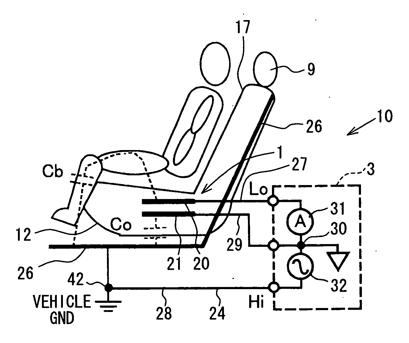
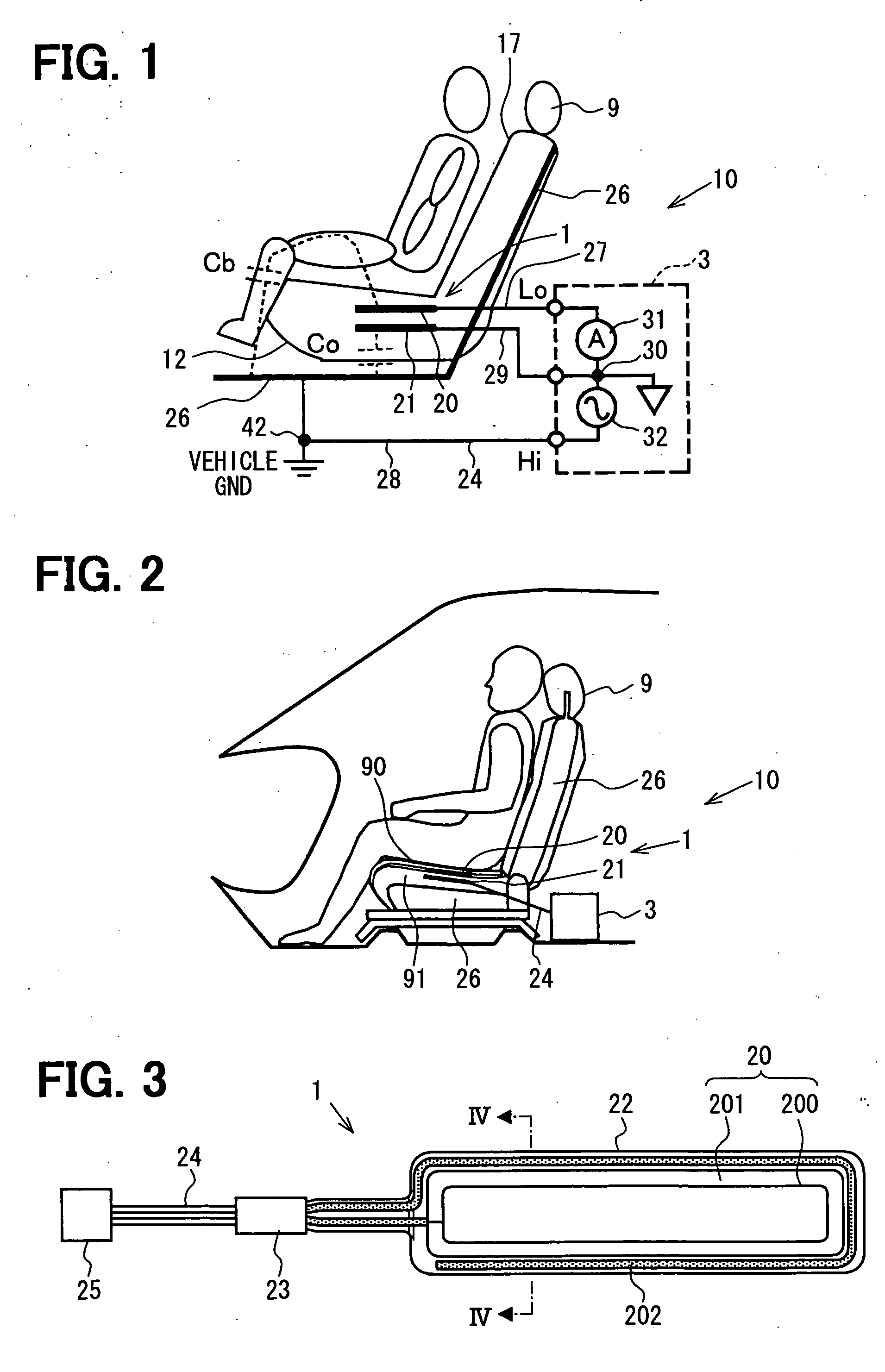
[0054]FIG. 1 is a diagram showing an overall structure of an occupant sensing system having a capacitance-based sensor 10 according to a first embodiment. FIG. 2 is a diagram showing a front passenger seat 9 to indicate an installation position of an electrode unit 1, which serves as a sensing device of the capacitance-based sensor 10.

[0055] As shown in FIG. 1, the capacitance-based sensor 10 of the present embodiment includes an occupant sensing electrode 20, an empty seat capacitance reducing electrode 21, an electric current sensing device (an electric current sensing circuit) 31 and a drive device (a drive circuit) 32. The occupant sensing electrode 20 is embedded in at least one of a seat bottom 12 and a seatback 17 of the front passenger seat 9, which serves as a vehicle seat of the present invention. In this particular embodiment, as shown in FIG. 1, the occupant sensing electrode 20 is embedded in the seat bottom 12. The empty seat capacitance reducing electrode 21 is oppos...

second embodiment

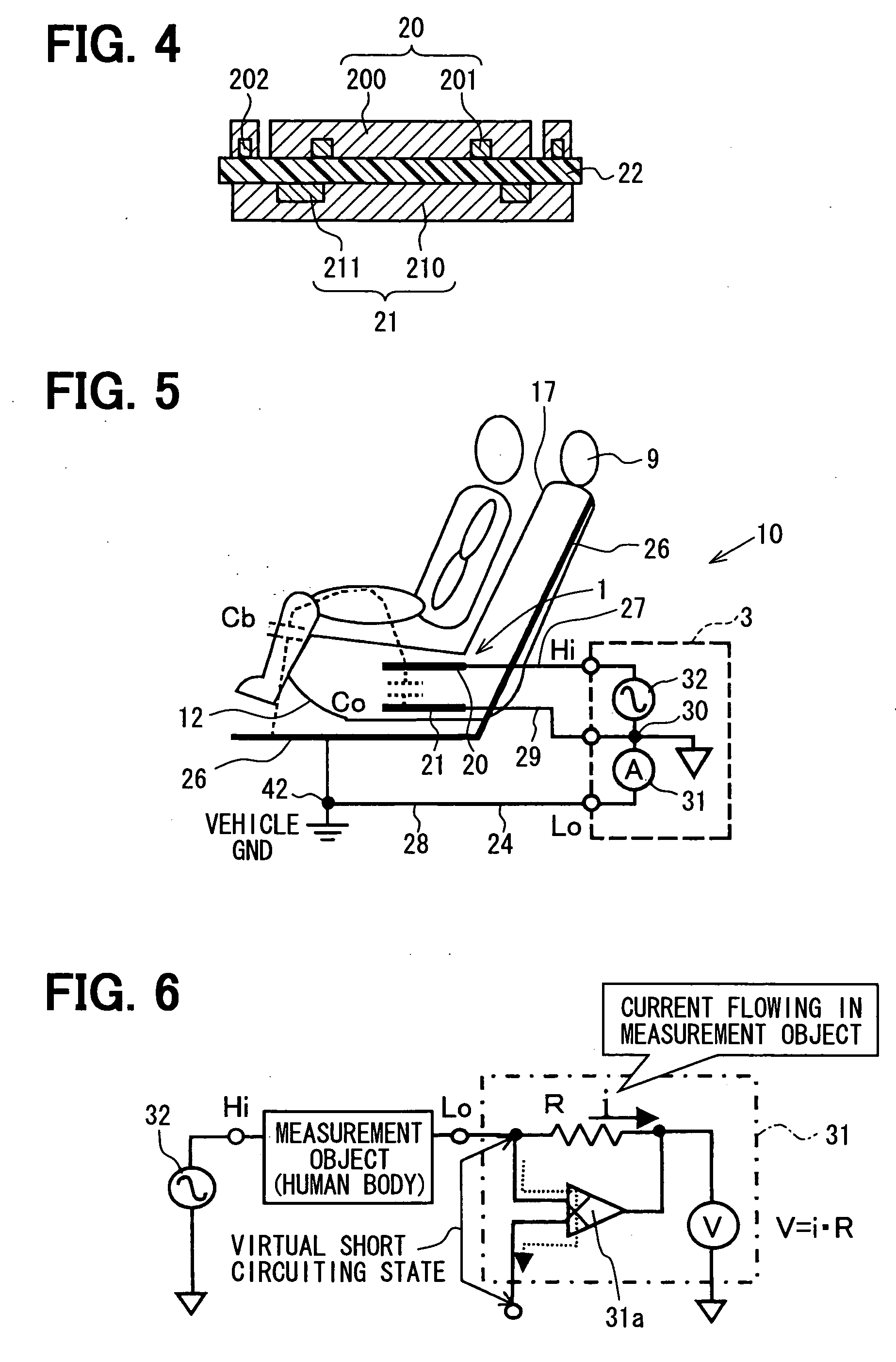
[0068] As shown in FIG. 5, a second embodiment is characterized in that the drive device 32 is electrically connected between the occupant sensing electrode 20 and the empty seat capacitance reducing electrode 21 at the depicted position (the first position of the present invention), and the electric current sensing device 31 is electrically connected between the vehicle GND 42 and the empty seat capacitance reducing electrode 21 and the drive device 32 at the depicted position (the second position of the present invention).

[0069] Operation of each part of the capacitance-based sensor 10 at the time of measuring the capacitance will be described with reference to FIG. 5. When the drive device 32, which is connected between the occupant sensing electrode 20 and the empty seat capacitance reducing electrode 21, generates the drive output of the high-frequency, low-voltage, the occupant sensing electrode 20 is driven to have a high electric potential. In this way, the capacitance Cb i...

third embodiment

[0071] A third embodiment is characterized in that the structure of the first or second embodiment is modified as follows. That is, as shown in FIG. 6, the electric current sensing device 31 has an operational amplifier 31a, which keep the same electric potential and electric insulation between the corresponding two electrodes, between which the electric current sensing device 31 is interposed. In this way, in the structure (the first embodiment) where the electric current sensing device 31 is connected between the occupant sensing electrode 20 and the empty seat capacitance reducing electrode 21, these electrodes 20, 21 can be made in the state (the virtual short-circuiting state) where the same electric potential and the electric insulation are effectively provided between the electrodes 20, 21 by the operational amplifier 31a. In this state, a voltage drop V caused by a resistance R is measured with a voltmeter. Based on the relationship of V=i·R, the electric current i, which fl...


PUM

PropertyMeasurementUnit
dielectric constantaaaaaaaaaa
capacitanceaaaaaaaaaa

Abstract

An occupant sensing electrode is embedded in a seat. An empty seat capacitance reducing electrode is placed between the occupant sensing electrode and a seat frame of the seat in an opposed relationship to the occupant sensing electrode. A dielectric base film may be interposed between the occupant sensing electrode and the empty seat capacitance reducing electrode. The occupant sensing electrode may include a plurality of electrode portions. The electrode portions may include high potential electrode portions and low potential electrode portions.

Description

CROSS REFERENCE TO RELATED APPLICATION [0001] This application is based on and incorporates herein by reference Japanese Patent Application No. 2005-15749 filed on Jan. 24, 2005, Japanese Patent Application No. 2005-40773 filed on Feb. 17, 2005 and Japanese Patent Application No. 2005-62738 filed on Mar. 7, 2005. BACKGROUND OF THE INVENTION [0002] 1. Field of the Invention [0003] The present invention relates to a capacitance-based sensor, which is embedded in a vehicle seat, and also relates to an occupant sensing system, which determines an occupant state of the seat based on an output of the capacitance-based sensor. [0004] 2. Description of Related Art [0005] One type of occupant sensing system includes a capacitance-based sensor and an occupant sensing electronic control unit (ECU). The capacitance-based sensor senses a disturbance in a weak electric field generated by an electrode and outputs the sensed result as the corresponding electric current or electric voltage (see, for...

Claims


Application Information

Patent Timeline
Patent Type & Authority Applications(United States)
IPC IPC(8): A47C31/00B60K28/04G01L5/04
CPCB60R21/01532B60N2/002
Inventor KAMIZONO, TSUTOMUWANAMI, SHINGOANDO, SHINJI
Owner DENSO CORP
Why Eureka
Try Eureka