

Device package structure, device packaging method, droplet ejection head, connector, and semiconductor device
- Summary
- Abstract
- Description
- Claims
- Application Information
AI Technical Summary
Benefits of technology
Problems solved by technology
Method used
Image

Examples
first embodiment
[0110] Hereunder is a description of embodiments of this invention with reference to drawings. However, this invention is not limited to the following embodiments. Moreover, in the respective drawings referred to in the following description, for the sake of simplicity of the drawing, the dimensions of the respective components are modified and the respective components are partially omitted.
[0111] Droplet Ejection Head
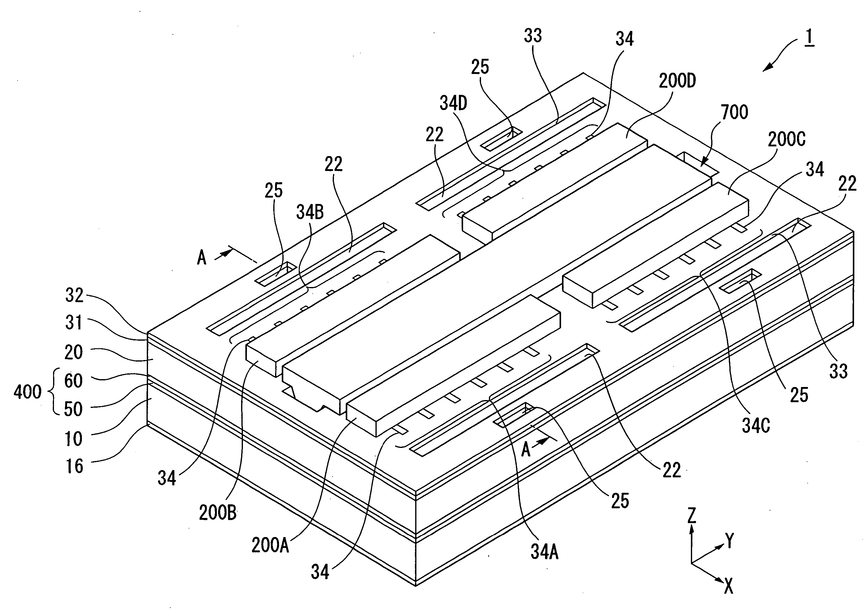
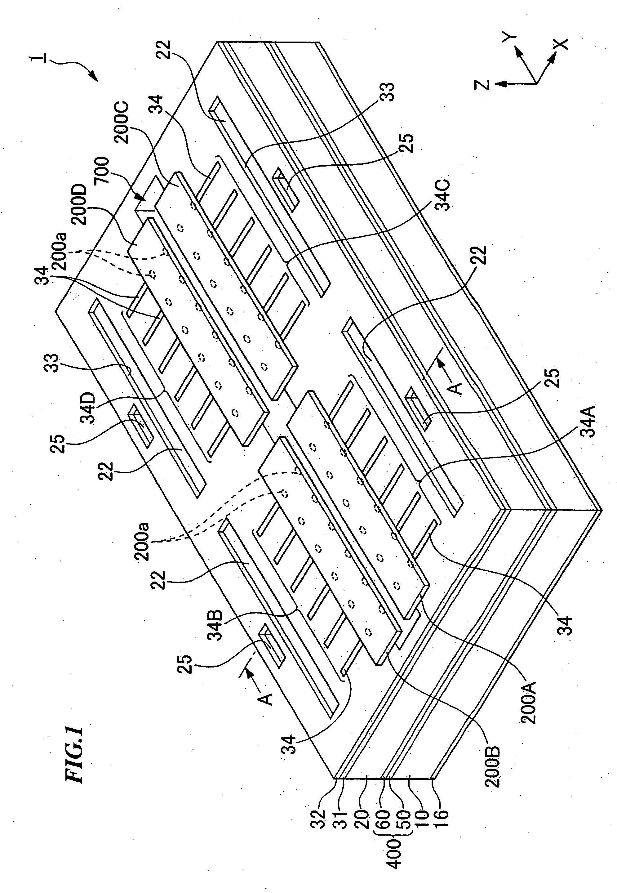
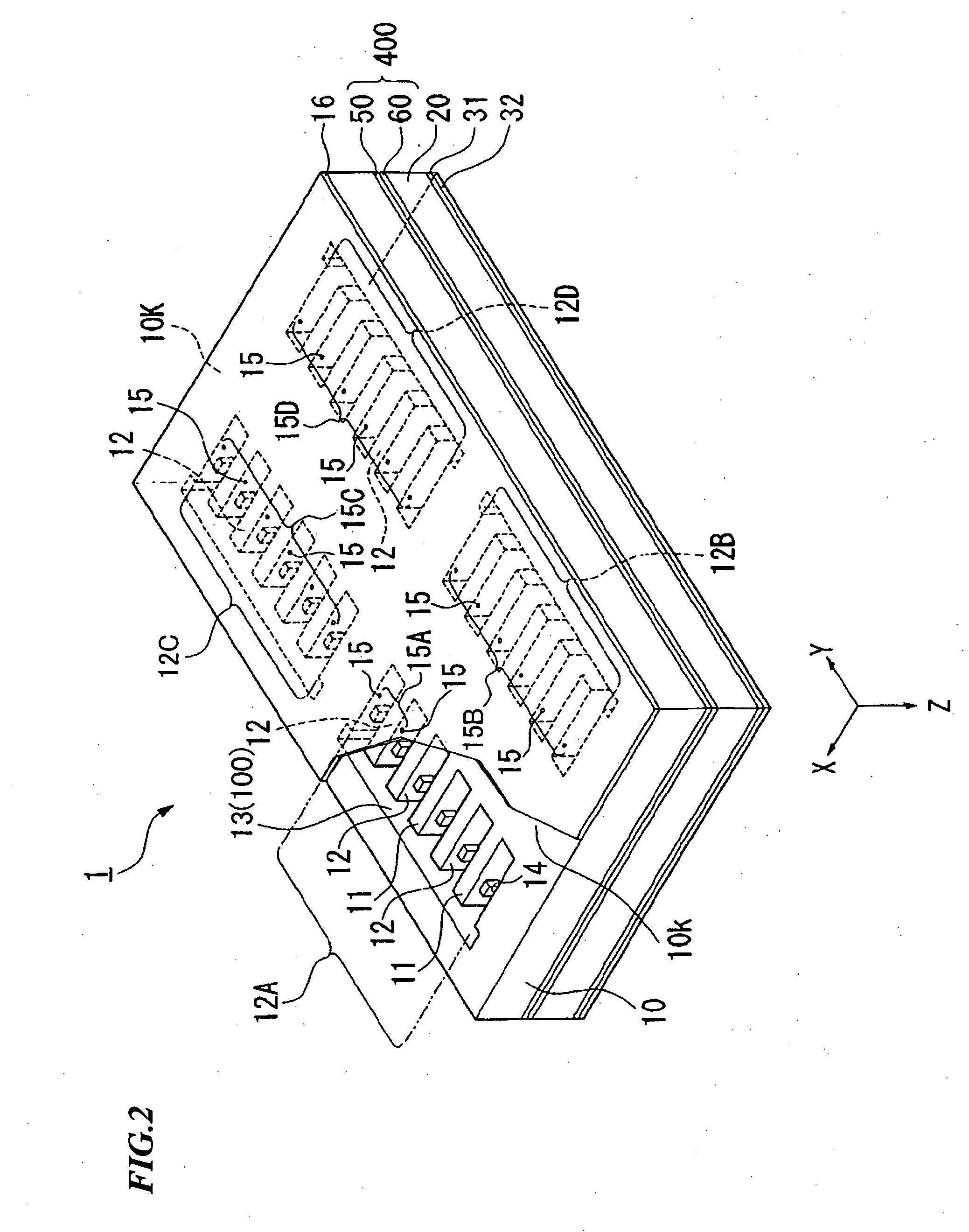
[0112] Firstly, as an embodiment of this invention, a droplet ejection head including a device package structure of this invention is described, with reference to FIG. 1 to FIG. 4. FIG. 1 is a schematic perspective view of an embodiment of the droplet ejection head. FIG. 2 is a partially exploded schematic perspective view of the droplet ejection head viewed from the bottom. FIG. 3 is a cross-sectional view of the droplet ejection head taken along the line A-A shown in FIG. 1.
[0113] In the following description, a XYZ rectangular coordinate system is set, and the p...
second embodiment
[0185] Next is a description of a second embodiment of this invention, with reference to FIG. 6. FIG. 6A is a cross-sectional view of the droplet ejection head of this embodiment, corresponding to FIG. 3 in the previous embodiment. FIG. 6B is a perspective view of the connector 360 shown in FIG. 6A.
[0186] The droplet ejection head of this embodiment has a characteristic in the configuration of the connector 360 arranged in the slot 700. The other configuration is similar to that of the droplet ejection head of the previous first embodiment. Consequently, hereunder, the configuration of the connector 360 is mainly described. Moreover, in FIG. 6, the same reference symbols as those of FIG. 1 to FIG. 3 are used for components common to the droplet ejection head of the previous embodiment, and detailed description thereof is omitted.
[0187] As shown in FIG. 6B, the connector 360 is configured including: a quadratic prism shaped connector base member 36a; a plurality of terminal electro...
third embodiment
[0227] Next is a description of a third embodiment of this invention with reference to FIG. 7. FIG. 7A is a cross-sectional view of the droplet ejection head of this embodiment, corresponding to FIG. 3 in the previous embodiment. FIG. 7B is a plan view of the flexible substrate 501 shown in FIG. 7A.
[0228] The droplet ejection head of this embodiment has a characteristic in the configuration where the driving circuit units 200A to 200D are packaged via the first flexible substrate 501, the second flexible substrate 502, and the third and fourth flexible substrates (not shown) on the connector 360 shown in FIG. 6B. Consequently, in the droplet ejection head of this embodiment, the configuration other than the package structure of the driving circuit units 200A to 200D is similar to that of the droplet ejection head of the second embodiment shown in FIG. 6. Therefore, in FIG. 7, the same reference symbols are used for components common to FIG. 6, and detailed description thereof is om...
PUM
 Abstract
Description
Claims
Application Information