Dielectric ceramic and multilayer ceramic capacitor
Active Publication Date: 2008-05-15
MURATA MFG CO LTD
View PDF7 Cites 57 Cited by
Summary
Abstract
Description
Claims
Application Information
AI Technical Summary
This helps you quickly interpret patents by identifying the three key elements:
Problems solved by technology
Method used
Benefits of technology
Benefits of technology
[0018] According to the dielectric ceramic of the present invention, a compound represented by the general formula: (Ba1-tCat)m(Ti1-u-xZruCux)O3 (where 0.96≦m≦1.02, 0.001≦x≦0.03, 0≦t≦0.1, and 0≦u≦0.06) is contained as a primary component, the Cu is substantially uniformly dispersed in the primary phase grain forming the primary component, and with respect to 100 molar parts of the primary component, 0.1 to 1.5 molar parts of Re, 0.1 to 0.6 molar parts of M, 0.1 to 1.5 molar parts of Mg, and 0.1 to 2.0 molar parts of Si are present contained. As a result, multilayer ceramic capacitor can be obtained which has a high relative dielectric constant, superior temperature properties of electrostatic capacitance, a superior reliability, and a small change in electrostatic capacitance with time.
[0019] In particular, a multilayer ceramic capacitor can be obtained in which the relative dielectric constant εr is 2,500 or more, the dielectric loss tan δ is less than 7%, the rate of change in electrostatic capacitance with temperature satisfies the B characteristics (the rate of change in electrostatic capacitance with temperature based on that at 20° C. is within ±10% in the range of −25 to +85° C.) of JIS, no defects are generated for 2,000 hours under high temperature load conditions, and the rate of change in electrostatic capacitance with time is within ±5%.
[0020] In addition, since the average value of the region in which the Re is solid-solved in the primary phase grain is set to 40% or less in terms of a cross-sectional area ratio, a multilayer ceramic capacitor can be obtained in which the temperature properties of electrostatic capacitance are further improved. In particular, the rate of change in electrostatic capacitance with temperature based on that at 20° C. in the range of −25 to +85° C. can be decreased to within ±7.5%.
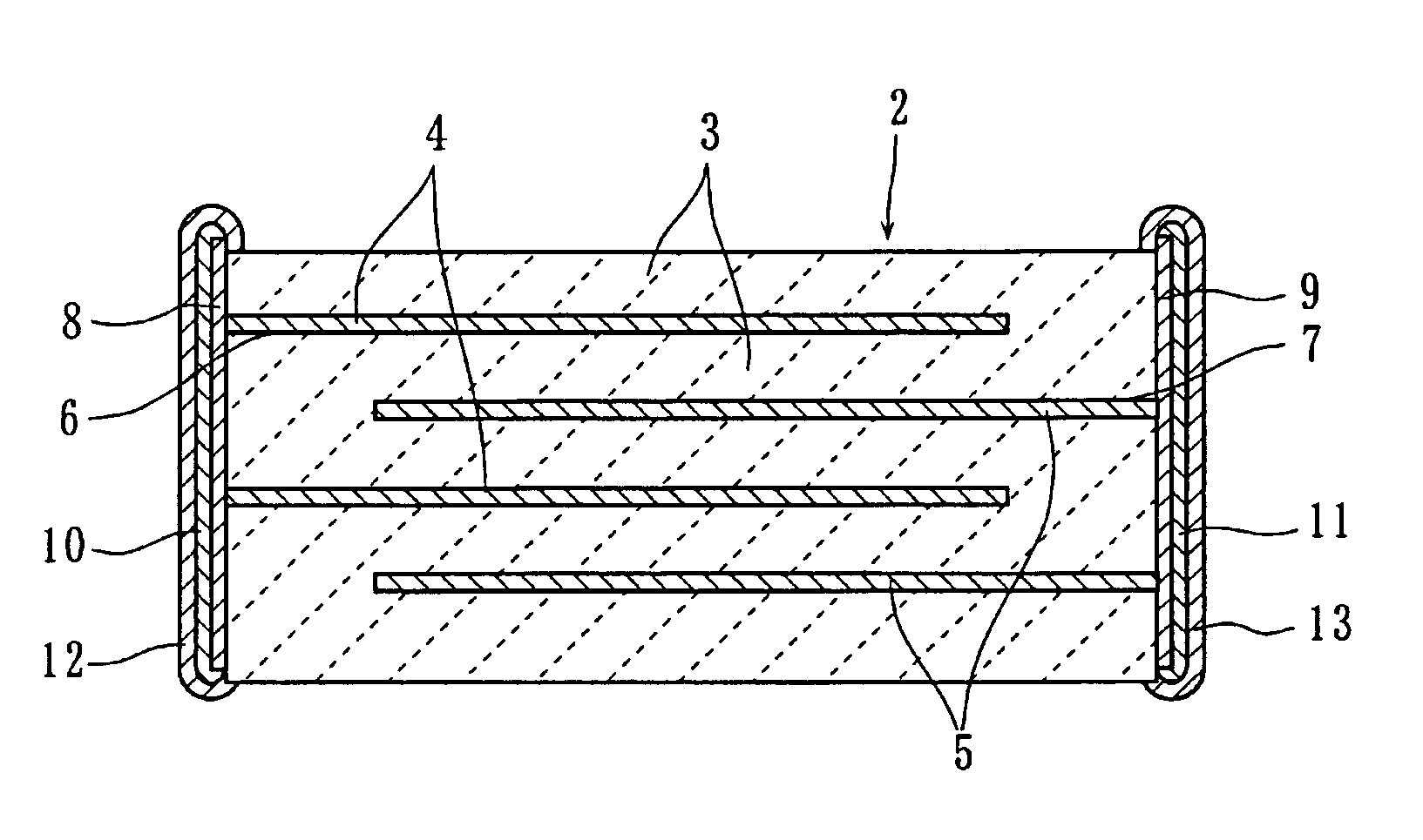
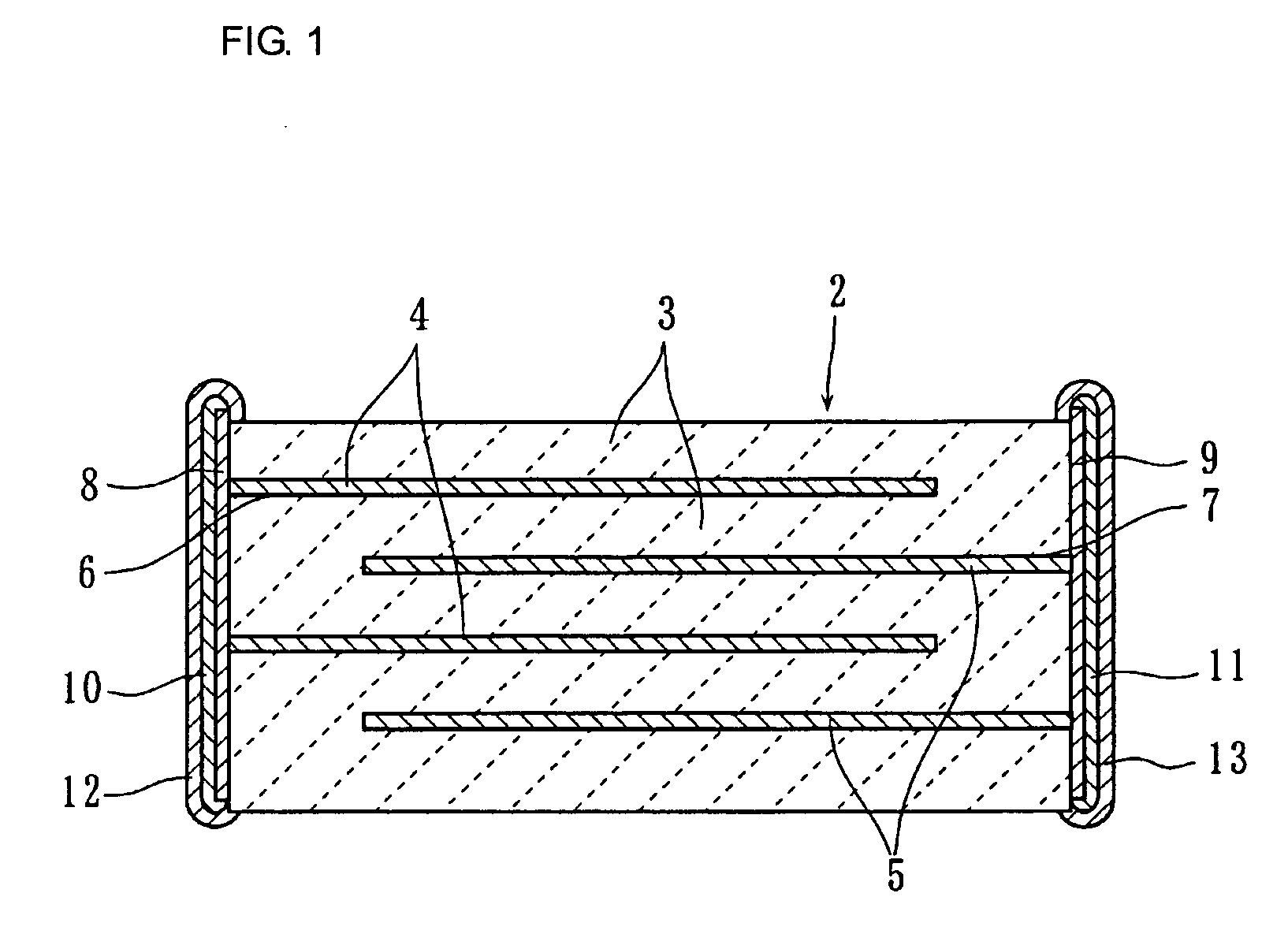
[0021] The multilayer ceramic capacitor including a multilayer sintered body formed by sintering a ceramic laminate composed of dielectric layers and internal electrodes alternately laminated to each other; and external electrodes formed on external surfaces of the multilayer sintered body, has the dielectric layers are formed from the dielectric ceramic described above. Hence, the desired multilayer ceramic capacitor can be obtained which has a high dielectric constant, superior temperature properties of electrostatic capacitance, a superior reliability, and a small change in electrostatic capacitance with time as described above.
Problems solved by technology
Hence, a decrease in the relative dielectric constant εr and a degradation in temperature properties may occur, and in addition, a dielectric breakdown between internal electrodes may also occur, so that the reliability may be degraded in some cases.
Method used
Image
Click on the blue label to locate the original text in one second.
Reading with bidirectional positioning of images and text.
Examples
example 1
[0086] In Example 1, the change in properties of a multilayer ceramic capacitor which was obtained when the composition of a dielectric ceramic and the solidsolution state of Cu were changed was confirmed.
[0087] First, as ceramic raw materials, powdered BaCO3, TiO2 and CuO were prepared and weighed to satisfy the compositions of Sample Nos. 1 to 31 shown in Table 1. Next, the weighed materials were charged in a ball mill containing PSZ (partly stabilized zirconia) balls, were mixed and pulverized, and were then dried, so that a mixed powder was obtained. Subsequently, this mixed powder was processed by a calcination treatment at 1,150° C. for 2 hours, and hence, a primary component powder represented by the general formula: Bam(Ti1-xCux)O3 was formed.
[0088] Next, powders of Dy2O3, Gd2O3, La2O3, Eu2O3, Pr6O11, Er2O3, CeO2, Nd2O3, Ho2O3, Sm2O3, Y2O3, Tb2O3, Lu2O3, Yb2O3 and Tm2O3 as a rare earthoxide containing a rare earth element Re, and powders of MnO, Fe2O3, V2O5, NiO, CO3O4, ...
[0126] After a ceramic laminate having the same composition as that of Sample No. 1 of Example 1 was formed and was then heated to 350° C. in a nitrogenatmosphere as a debinder treatment, firing was performed in a reducing atmosphere of a H2—N2—H2O gas at an oxygenpartial pressure of 10 MPa and at a temperature in the range of 980 to 1,250° C. for 2 hours, so that a multilayer sintered body including internal electrodes therein was formed. Subsequently, by a method and procedure similar to those of Example 1, multilayer ceramic capacitors of Sample Nos. 41 to 48 were formed.
[0127] Next, after the samples of Samples Nos. 41 to 48 were cut, the cross-sections thereof were observed using a FE-TEM-EDX in a manner similar to that in Example 1, so that the solid-solution area ratio of Dy in the primary phase grain was obtained. That is, 20 crystal grains we...
example 3
[0133] In Example 3, the influences of the molar ratio t of Ca in the B site and the molar ratio u of Zr in the Ti site were confirmed.
[0134] First, as ceramic raw materials, powdered BaCO3, TiO2, and CuO were prepared and weighed to satisfy the compositions of Sample Nos. 51 to 68 shown in Table 4. Next, the weighed materials were charged in a ball mill containing PSZ balls, were mixed and pulverized, and were then dried, so that a mixed powder was obtained. Subsequently, this mixed powder was processed by a calcination treatment at 1,150° C. for 2 hours, and hence, a primary component powder represented by the general formula: (Ba1-tCat)1.010(Ti0.090-uZruCu0.010)O3 was formed.
[0135] Next, with respect to 100 molar parts of the primary component, 1.0 molar part of Dy2O3, 0.3 molar parts of MnO, 1.0 molar part of MgO, and 1.0 molar part of SiO2 were added and were then mixed together in a ball mill containing PSZ balls, followed by drying, so that a ceramic material powder was obt...
PUM
Property
Measurement
Unit
Fraction
aaaaa
aaaaa
Mass
aaaaa
aaaaa
Length
aaaaa
aaaaa
Abstract
A dielectricceramic includes a compound represented by the general formula: (Ba1-tCat)m(Ti1-u-xZruCux)O3 (where 0.96≦m≦1.02, 0.001≦x≦0.03, 0≦t≦0.1, and 0≦u≦0.06) as a primary component, a rare earth element Re such as Dy, a metal element M such as Mn, Mg, and Si. In the dielectricceramic, the Cu is uniformly and dispersedly present in the primary phase grain forming the primary component, and the contents of the accessory components with respect to 100 molar parts of the primary component are 0.1 to 1.5 molar parts of Re, 0.1 to 0.6 molar parts of M, 0.1 to 1.5 molar parts of Mg and 0.1 to 2.0 molar parts of Si. Accordingly, a multilayer ceramiccapacitor can be realized which has a high dielectric constant, superior temperature properties, and a high reliability, and also has a small change in electrostatic capacitance with time.
Description
[0001] This is a continuation of application Serial No. PCT / JP2006 / 310321, filed Mary 24, 2006.TECHNICAL FIELD [0002] The present invention relates to a dielectric ceramic and a multilayer ceramic capacitor, and more particularly relates to a dielectric ceramic which is suitably used as a dielectric material for forming a compact and large-capacity multilayer ceramic capacitor and to a multilayer ceramic capacitor manufactured by using the above dielectric ceramic. BACKGROUND ART [0003] Concomitant with recent developments in electronic techniques, a reduction in size and an increase in capacitance of multilayer ceramic capacitors have increasingly advanced. [0004] This type of multilayer ceramic capacitor is manufactured by the steps of forming a ceramic laminate by alternately laminating internal electrodes and dielectric layers each composed of a dielectric ceramic containing BaTiO3 or the like as a primary component, performing a firing treatment on the ceramic laminate to form ...
Claims
Application Information
Patent Timeline
Application Date:The date an application was filed.
Publication Date:The date a patent or application was officially published.
First Publication Date:The earliest publication date of a patent with the same application number.
Issue Date:Publication date of the patent grant document.
PCT Entry Date:The Entry date of PCT National Phase.
Estimated Expiry Date:The statutory expiry date of a patent right according to the Patent Law, and it is the longest term of protection that the patent right can achieve without the termination of the patent right due to other reasons(Term extension factor has been taken into account ).
Invalid Date:Actual expiry date is based on effective date or publication date of legal transaction data of invalid patent.

