Method of motion correction in optical coherence tomography imaging
- Summary
- Abstract
- Description
- Claims
- Application Information
AI Technical Summary
Benefits of technology
Problems solved by technology
Method used
Image
Examples
Embodiment Construction
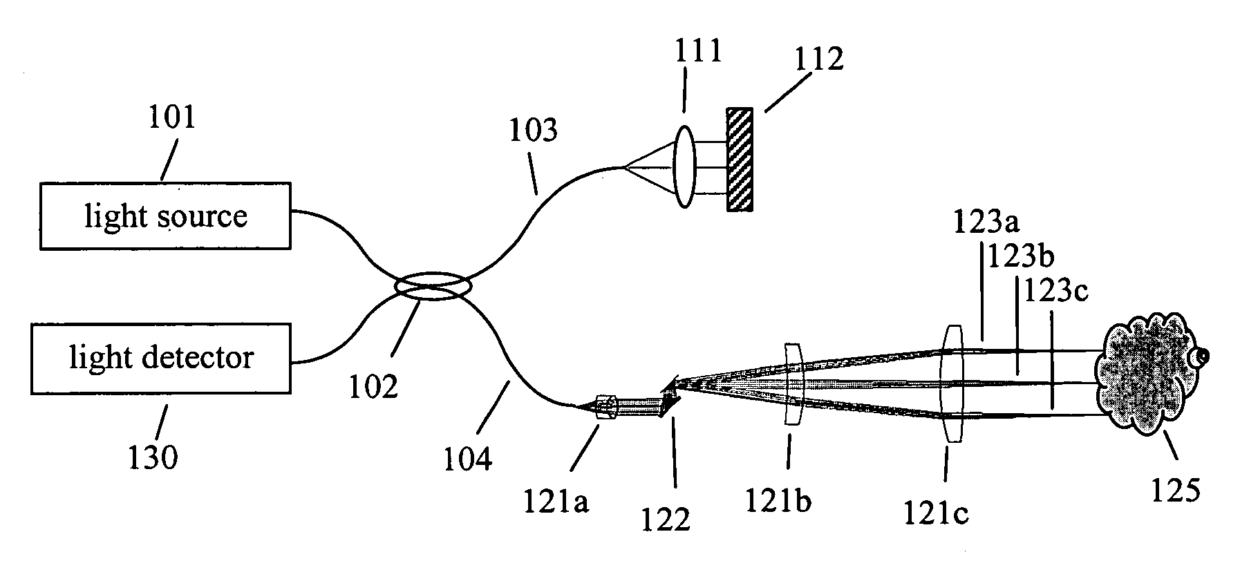
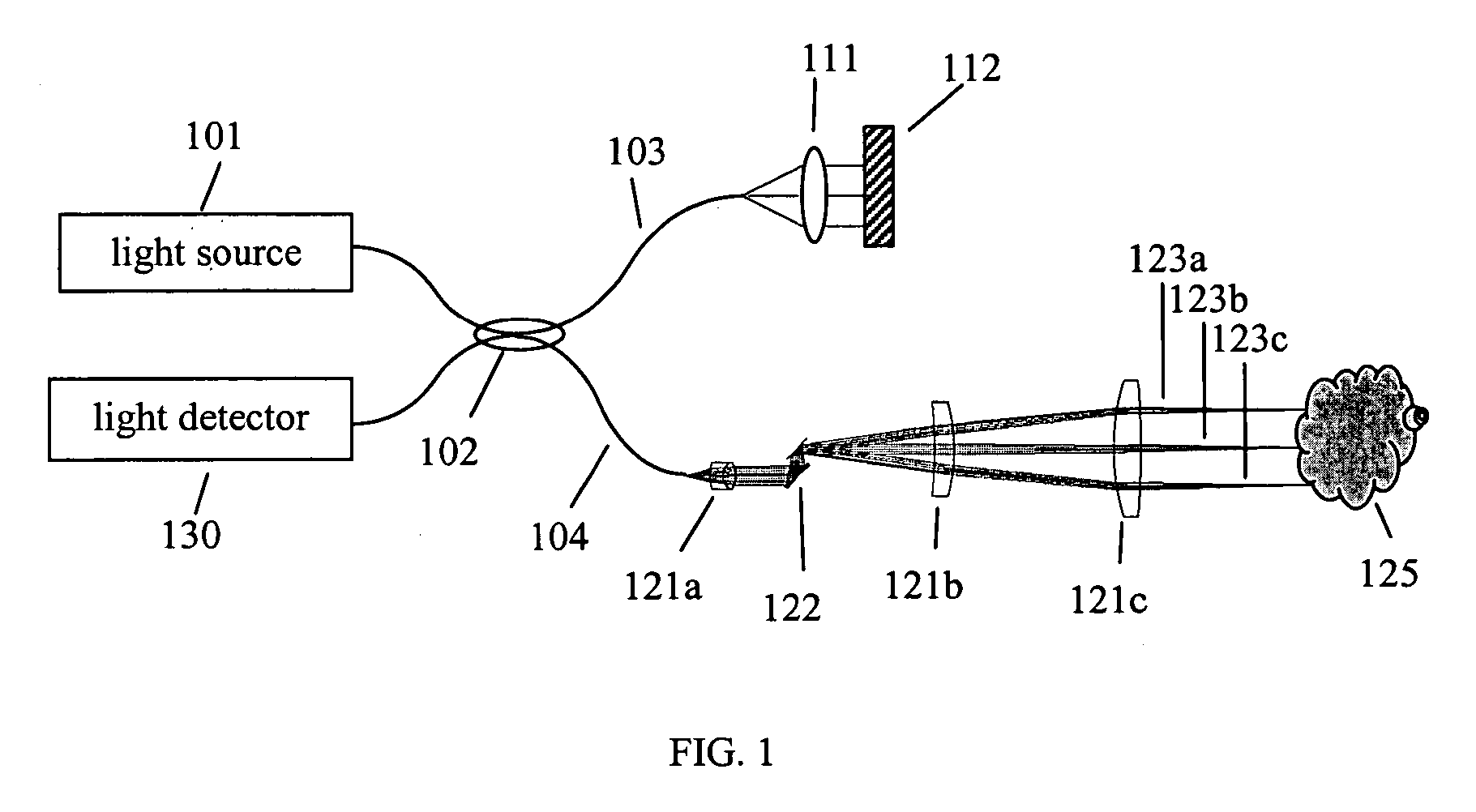
[0016]FIG. 1 is a schematic illustration of one design of OCT system. The light source 101 provides light having a short-coherence length to the fiber-based interferometer. Directional coupler 102 serves to split the light from source 101 between a reference arm 103 and a sample arm 104. Lens 111 and mirror 112 serve to return reference light back to coupler 102. A scanning system including lenses 121a, 121b, and 121c, and scanning mirrors 122, directs light successively along paths such as 123a, 123b, 123c onto successive locations on sample 125. Some light scattered from sample 125 returns closely enough along the illumination path to re-enter the fiber interferometer, is combined with reference light in coupler 102. The interfered sample and reference light are detected in detector 130.
[0017] The scanning mirror 122 is controlled by a system processor and generates scan coordinates which correspond to certain transverse positions on the sample. A sample, such as the human eye, w...
PUM
 Abstract
Description
Claims
Application Information
 - R&D
- Intellectual Property
- Life Sciences
- Materials
- Tech Scout
- Unparalleled Data Quality
- Higher Quality Content
- 60% Fewer Hallucinations
Browse by: Latest US Patents, China's latest patents, Technical Efficacy Thesaurus, Application Domain, Technology Topic, Popular Technical Reports.
© 2025 PatSnap. All rights reserved.Legal|Privacy policy|Modern Slavery Act Transparency Statement|Sitemap|About US| Contact US: help@patsnap.com


