Light emitting apparatus

a technology of light emitting apparatus and light source, which is applied in the direction of lighting and heating apparatus, semiconductor/solid-state device details, lighting support devices, etc., can solve the problems of reducing the light emission efficiency of the apparatus, affecting the efficiency of light emission, so as to achieve the effect of increasing the heat radiation area and high thermal conductivity

Inactive Publication Date: 2006-07-27
TOYODA GOSEI CO LTD
View PDF26 Cites 67 Cited by
  • Summary
  • Abstract
  • Description
  • Claims
  • Application Information

AI Technical Summary

Problems solved by technology

The reflection-type light emitting apparatus has a problem that part of light is blocked by the LED element and a lead for power supply that are located on an optical path of reflected light, although it has good light radiation efficiency since the reflection-type light emitting apparatus can focus light in high efficiency.
As a result, a considerable amount of heat generation occurs in the LED element.
However, if the lead is enlarged to cope with an increase in heat generation, light emission efficiency of the apparatus must lower since the reflected light is blocked by the enlarged lead.
Thus, there is a barrier in enhancing the light emission efficiency.

Method used


Image

  • Light emitting apparatus
  • Light emitting apparatus
  • Light emitting apparatus

Examples


first embodiment

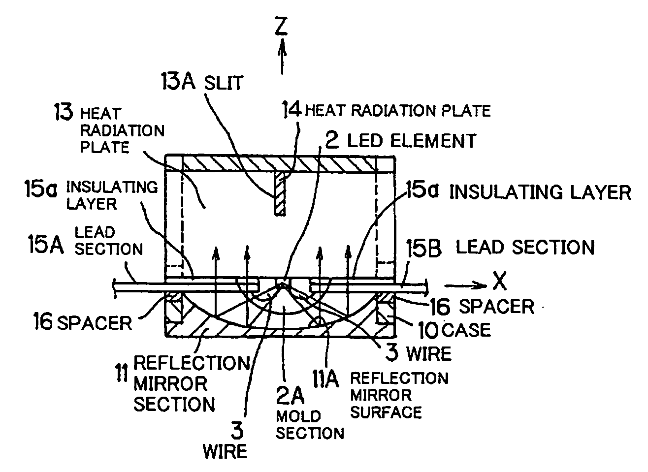
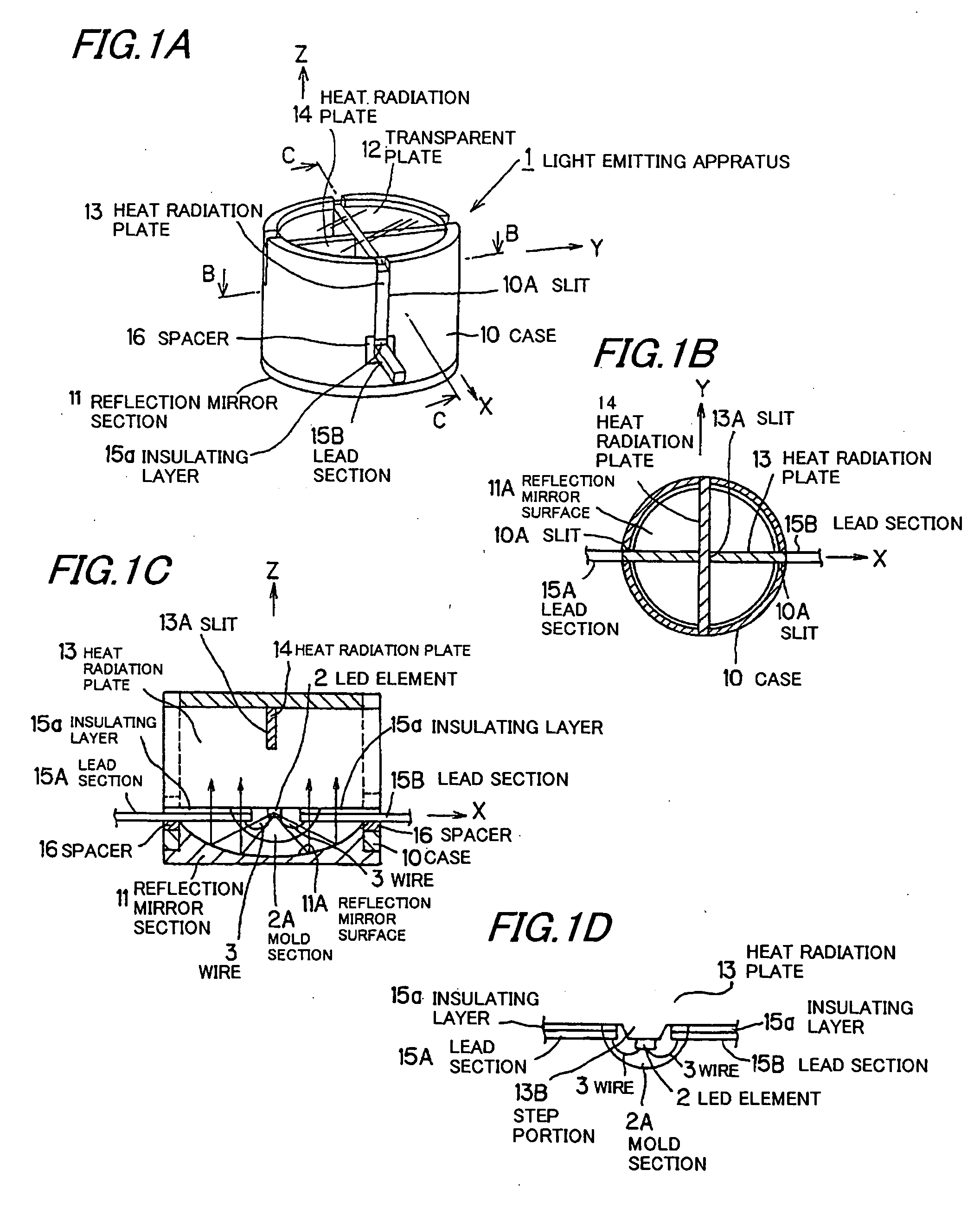
[0110] Although in the first embodiment the GaN based LED element 2 is used, the other LED elements such as an AlInGaP may be used.

[0111] The reflection-type light emitting apparatus may be a wavelength conversion type that its mold section 2A to seal the LED element 2 contains a phosphor. In this case, since in the reflection-type optical system the refractive index does not change depending on emission wavelength unlike a lens-type LED, color separation is not generated in focused light.

[0112] For example, a white light source is composed of spectrum lights with a plurality of wavelength regions such as blue light from LED and yellow light from a phosphor excited by the blue light, or blue, green, and red lights from phosphors excited by UV light from LED. In the case that such light is focused by and radiated through a lens, the refractive index of light changes with its wavelength and, therefore, light is radiated in different directions. This phenomenon becomes more significan...

fifth embodiment

[0153] Although in the fifth embodiment the convex section 11B is formed integrated with the reflection mirror surface 11A, the convex section 11B may be, for example, formed separated from the reflection mirror surface 11A to be bonded to the reflection mirror surface 11A through an adhesive or the like.

(6) Sixth Preferred Embodiment

[0154]FIG. 7 is a partial structure view showing a mold section 2A in the sixth preferred embodiment of the present invention.

[0155] The mold section 2A has a concave section 2a that is concaved in an arc form on the side of light radiation surface of the LED element 2.

[0156] In the sixth preferred embodiment, light emitted directly under the LED element 2 is refracted when radiated from the concave section 2a to outside of the mold section 2A. Namely, since light does not enter into part of the reflection mirror surface 11A placed directly under the LED element 2, the light extraction property of reflected light can be enhanced.

(7) Seventh Preferre...

ninth embodiment

[0206] Halogen bulbs lower than 10 W are difficult to embody in technical aspect since they do not have sufficient halogen cycle even when the commercialization thereof is needed. However, as above explained in the ninth embodiment, the small LED spot light source in several W class can be embodied with an excellent integration performance by arranging densely the cellular multiple light emitting sections in parallel. Furthermore, since light radiated from the LED light source does not contain heat ray, it has a property that an irradiated object such as chocolate and lipstick does not melt even when it is closely illuminated thereby. The light emitting section may be arranged in spherical form other than in planar form.

[0207] Since R, G and B lights are externally radiated, through the reflection of reflection mirror surface 11A, from the light emitting sections 1R, 1G and 1B placed closely in the case 10, the R, G and B lights can be irradiated to a nearly identical region at a pl...


PUM

PropertyMeasurementUnit
refractive indexaaaaaaaaaa
poweraaaaaaaaaa
turn-on poweraaaaaaaaaa

Abstract

A reflection-type light emitting apparatus has an excellent heat radiation property and allows the use of a high-power light emitting element, the minimization of a reduction in radiation efficiency of reflected light, and the focused radiation of high-output light at high efficiency. The apparatus has: a case 10 of metallic material and with an excellent heat radiation property; a reflection mirror section 11 formed fitted to the lower portion of case 10; a transparent plate 12 to cover the upper surface of case 10; heat radiation plates 13, 14 of metallic material with excellent heat conductivity and inserted inside the case 10; an LED element 2 mounted on the heat radiation plate 13; lead sections 15A, 15B fixed through an insulating layer 15a to the heat radiation plate 13 to serve as a power supply member to supply power to the LED element 2; and a spacer 16 of an insulating material to insulate the lead sections 15A, 15B from the case 10.

Description

[0001] The present application is based on Japanese patent application Nos. 2003-373274 and 2004-251021, the entire contents of which are incorporated herein by reference. TECHNICAL FIELD [0002] The present invention relates to a light emitting apparatus and, in particular, to a reflection-type light emitting apparatus that reflects light emitted from a light emission surface of a light source and radiates the reflected light to the backside of the light source. BACKGROUND ART [0003] Japanese patent application laid-open No. 5-291627 discloses a reflection-type light emitting apparatus in which an LED (Light Emitting Diode) element is located opposite to a reflection mirror so as to reflect light emitted from the LED element and emit the reflected light in a desired direction. The reflection-type light emitting apparatus has a problem that part of light is blocked by the LED element and a lead for power supply that are located on an optical path of reflected light, although it has g...

Claims


Application Information

Patent Timeline
Patent Type & Authority Applications(United States)
IPC IPC(8): F21V29/00F21V29/505H01L33/50H01L33/32H01L33/56H01L33/60H01L33/62H01L33/64
CPCF21K9/00F21V29/89F21V7/06F21V7/08F21V7/22F21V15/01F21V29/004F21V29/2212F21Y2101/02H01L33/483H01L33/60H01L33/642H01L2224/13H01L2224/48091F21V7/0008F21V29/507F21V29/505H01L2924/00014F21Y2115/10F21K9/68H01L2924/00011F21V29/74F21V7/24F21V7/28H01L2224/0401
Inventor SUEHIRO, YOSHINOBUWADA, SATOSHIOTA, AKIHITO
Owner TOYODA GOSEI CO LTD
Why Eureka
Try Eureka