Eureka AIR delivers breakthrough ideas for toughest innovation challenges, trusted by R&D personnel around the world.

Inverter

Inactive Publication Date: 2006-07-27
TDK CORPARATION
View PDF1 Cites 2 Cited by
  • Summary
  • Abstract
  • Description
  • Claims
  • Application Information

AI Technical Summary

Benefits of technology

[0007] The present invention provides an inverter circuit for converting a direct current to an alternating current, having: a switching element, an inductance, a transformer, a first capacitor, and a controller. The switching element is connectable between a higher potential terminal and a lower potential terminal of a direct-current power supply. The inductance is connected between the higher potential and the switching element. The tran

Problems solved by technology

Thus, reduction of the number of parts, downsizing of the circuit configuration, and reduction of cost are problems to be solved.

Method used


Image

  • Inverter
  • Inverter
  • Inverter

Examples


Embodiment Construction

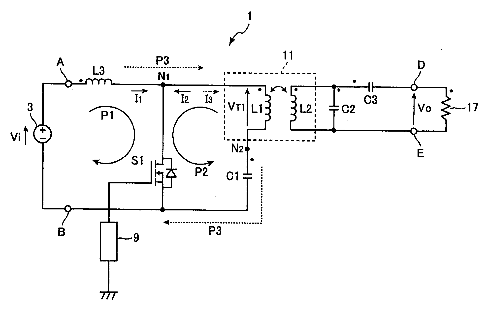
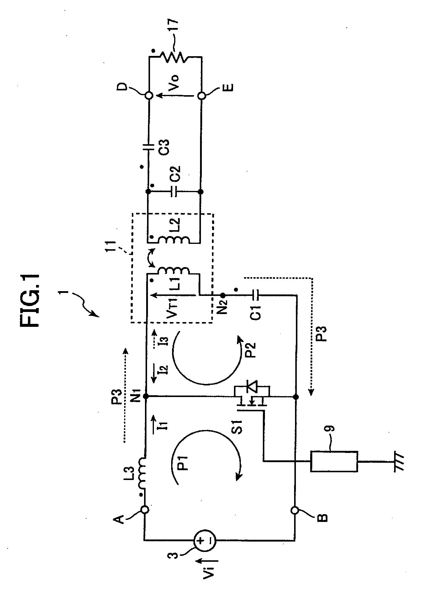
[0013] An embodiment according to the present invention will be described below with reference to FIGS. 1-3.

[0014] Referring to FIG. 1, an inverter circuit 1 according to the present invention includes a direct-current power supply 3, an inductor L3, a switching element S1, a capacitor C1, a transformer 11, capacitors C2, C3, and a controller 9.

[0015] The direct-current power supply 3 is a power supply that produces a direct-current voltage having a predetermined value V1. The direct-current power supply 3 has terminals A, B to output the direct-current voltage. The terminal A has a higher potential than the terminal B. The terminal B is connected to a reference potential G1. A direct current of a predetermined current value flows from the direct-current power supply 3 through the terminals A, B. Alternatively, the direct-current power supply 3 may be configured by a commercial alternating-current power supply and a rectifying circuit to produce a direct-current flow.

[0016] An in...


PUM


Abstract

An inverter circuit has a switching element, an inductance, a transformer, a capacitor, and a controller. The switching element is connectable between a higher potential terminal and a lower potential terminal of a direct-current power supply. The inductance is connected between the higher potential terminal and the switching element. The transformer has a primary winding and a secondary winding. The secondary winding has two ends. The capacitor is connected to the primary winding in series. The series-connected capacitor and primary winding is connected in parallel to the switching element. The controller switches the switching element. Therefore, the inverter circuit converts a direct current supplied from the direct-current power supply to an alternating current. The number of switching element in the inverter circuit is only one so that the structure of the inverter circuit is simplified and the manufacturing cost thereof can be reduced.

Description

BACKGROUND OF THE INVENTION [0001] 1. Technical Field [0002] The present invention relates to an inverter circuit that converts a direct current to an alternating current and outputs the converted alternating current. In particular, the present invention relates to an inverter circuit which is employed as a power supply circuit of various electronics devices including a backlight for a liquid crystal display. [0003] 2. Related Art [0004] Japanese Patent Application Publication Hei 5-343190 discloses an inverter circuit including a pair of transistors as switching elements and a transformer. A direct current is supplied to a middle point of a transformer and respective bases of the transistors through a resistor. In the inverter circuit, the paired transistors are alternately switched with a resonance frequency which is determined by an inductance of the transformer and capacities of two capacitors. Accordingly, an alternating current having a predetermined frequency depending on the...

Claims


Application Information

Patent Timeline
IPC IPC(8): H02M3/335H05B41/24H02M7/48
CPCH02M3/33507H02M2001/0058Y02B70/1491H02M1/0058Y02B70/10
Inventor UEMATSU, TAKESHI
Owner TDK CORPARATION
Why Eureka
Eureka Blog
Learn More