Organic light emitting diode display device

a technology of light-emitting diodes and display devices, which is applied in the direction of static indicating devices, instruments, etc., can solve the problems that the oled display cannot apply the low power mode the inability of the mobile lcd to arbitrarily adjust the luminance, etc., to prevent the rapid change of the luminance of the display panel and the luminance of pixels.

Active Publication Date: 2013-04-04
LG DISPLAY CO LTD
View PDF4 Cites 70 Cited by
  • Summary
  • Abstract
  • Description
  • Claims
  • Application Information

AI Technical Summary

Benefits of technology

[0008]Embodiments of the invention provide an organic light emitting diode (OLED) display capable of preventing rapid changes in the luminance of pixels when the operation mode of the OLED display changes from a low power mode to a normal mode.
[0009]In one embodiment, an OLED display comprises a display panel including data lines, scan lines intersecting with the data lines, and a plurality of pixels each of which includes an organic light emitting diode and are arranged in a matrix form; a power generator configured to generate a first voltage as a supply voltage for driving the pixels of the display panel in a first mode (e.g., normal operation mode) of the OLED display and is disabled in a second mode (e.g., lower power operation mode) of the OLED display; and a panel driving circuit configured to dri...

Problems solved by technology

In the low power mode, because the mobile LCD displays previously determined data by reflecting external light like a reflective LCD...

Method used


Image

  • Organic light emitting diode display device
  • Organic light emitting diode display device
  • Organic light emitting diode display device

Examples


Embodiment Construction

[0023]Reference will now be made in detail to embodiments of the invention, examples of which are illustrated in the accompanying drawings. Wherever possible, the same reference numbers will be used throughout the drawings to refer to the same or like parts.

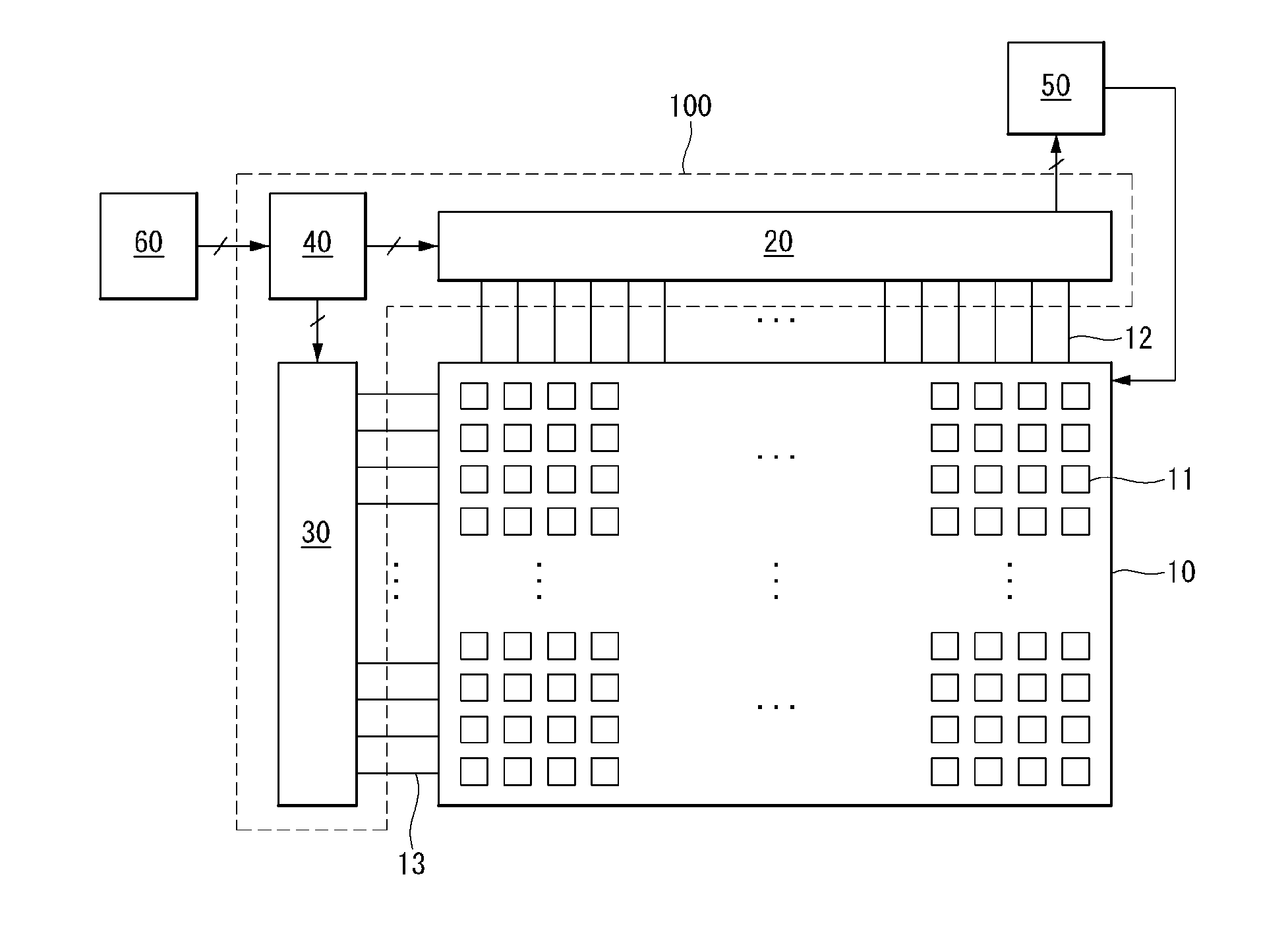
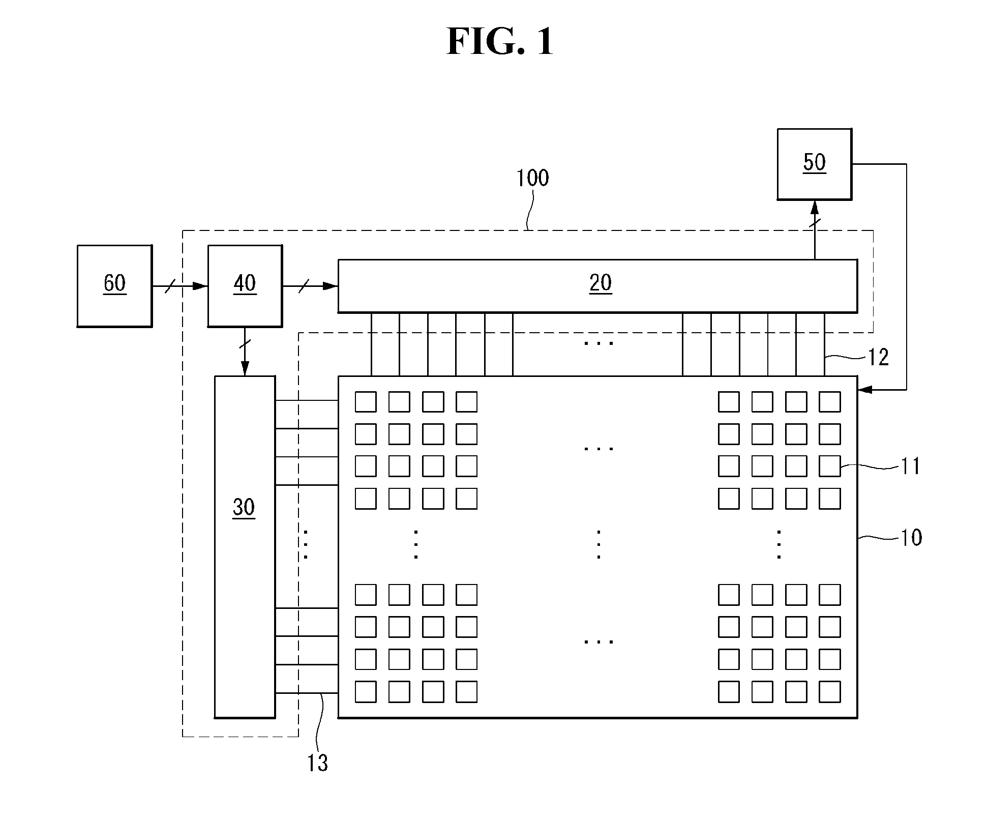
[0024]As shown in FIGS. 1 to 3, an organic light emitting diode (OLED) display according to an embodiment includes a display panel 10, a data driver 20, a scan driver 30, a power generator 50, and a timing controller 40.

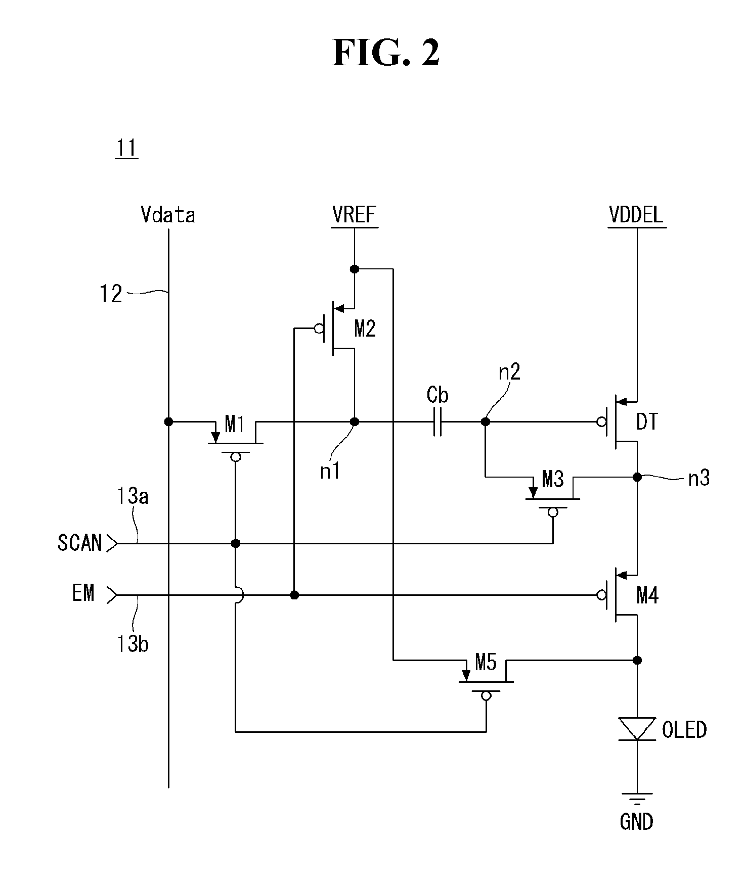
[0025]The display panel 10 includes data lines 12 for receiving a data voltage, scan lines 13 which intersect with the data lines 12 and sequentially receive a scan pulse SCAN and a light emitting control pulse EM, and pixels 11 arranged in a matrix form. The pixels 11 receive a high potential power voltage VDDEL as a pixel driving voltage. As shown in FIG. 2, each of the pixels 11 includes a plurality of thin film transistors (TFTs), a capacitor Cb, and an OLED. The pixel 11 is initialized in response to the scan...


PUM


Abstract

An organic light emitting diode (OLED) display includes a display panel including data lines, scan lines crossing the data lines, and pixels which each include an organic light emitting diode and are arranged in a matrix form, a power generator which is enabled in a normal mode to generate a high potential power voltage for driving the display panel and is disabled in a low power mode, and a panel driving circuit which drives the data lines and the scan lines, disables the power generator in the low power mode to cut off an output of the power generator, and supplies an internal power less than the high potential power voltage to the display panel to reduce the high potential power voltage in the low power mode.

Description

CROSS-REFERENCE TO RELATED APPLICATION[0001]This application claims the benefit of Korean Patent Application No. 10-2011-0099237 filed on Sep. 29, 2011, the entire contents of which is incorporated herein by reference for all purposes as if fully set forth herein.BACKGROUND OF THE INVENTION[0002]1. Field of the Invention[0003]Embodiments of the invention relate to an organic light emitting diode (OLED) display.[0004]2. Discussion of the Related Art[0005]Various flat panel displays (FPDs), that may replace cathode ray tubes (CRTs), have been developed. Examples of the FPDs include a liquid crystal display (LCD), a field emission display (FED), a plasma display panel (PDP) display, and an organic light emitting diode (OLED) display.[0006]A mobile LCD using MIPI (Mobile Industry Processor Interface) supports a low power mode for low power drive. The low power mode has been known as a partial idle mode (PIM) or a dimmed low power (DLP) mode. In the low power mode, the mobile LCD operate...

Claims


Application Information

Patent Timeline
IPC IPC(8): G09G3/32
CPCG09G3/3208G09G2320/02G09G2330/04G09G2330/028G09G2330/025G09G2340/0435G09G2330/021G09G3/30
Inventor LEE, HYUNJAE
Owner LG DISPLAY CO LTD
Why Eureka
Try Eureka