Power Supply Device, Control Method of Power Supply Device, and Motor Vehicle Equipped with Power Supply Device

a power supply device and control method technology, applied in the direction of electric devices, emergency power supply arrangements, vehicle sub-unit features, etc., can solve the problems of undesirable adjustment of the states of charge of such multiple batteries, and achieve the effects of high dischargeable electric power, fast deterioration, and favorable charge sta

Inactive Publication Date: 2009-01-15
TOYOTA JIDOSHA KK
View PDF5 Cites 68 Cited by
  • Summary
  • Abstract
  • Description
  • Claims
  • Application Information

AI Technical Summary

Benefits of technology

[0014]Under condition of no supply of electric power generated by the generator that consumes the output power of the internal combustion engine for power generation, the motor vehicle of the invention adjusts the first voltage and the second voltage, based on the detected state of the first battery. The first voltage represents the voltage of the first voltage system connected with the first battery that is chargeable and dischargeable and has the first characteristic. The second voltage represents the voltage of the second voltage system connected with the second battery that is chargeable and dischargeable and has the second characteristic different from the first characteristic. The adjustment of the first voltage and the second voltage aims to cause transmission of electric power between the first battery and the second battery and make the first battery have the favorable state of charge. This arrangement of the invention enables the first battery to have the favorable state of charge and ensures the adequate supply of electric power to a motor that outputs driving power for driving the motor vehicle.
[0015]In the motor vehicle of the invention, the power supply device may further include a second state detection unit that detects a state of the second battery, and the control module may control the voltage adjustment structure based on the state of the first battery detected by the first state detection unit and the state of the second battery detected by the second state detection unit to cause transmission of electric power between the first battery and the second battery and make the first battery have a favorable state of charge. In this case, the control module may control the voltage adjustment structure based on the state of the first battery detected by the first state detection unit and the state of the second battery detected by the second state detection unit to cause transmission of electric power between the first battery and the second battery and make both the first battery and the second battery have respective favorable states of charge. Further, the second characteristic may be quick deterioration in a high state of charge having a high level of dischargeable electric power, and the control module may control the voltage adjustment structure to shift the state of the second battery to a lower state of charge.
[0016]In the motor vehicle of the invention, the first characteristic may be quick deterioration in a low state of charge having a low level of dischargeable electric power, and the control module may control the voltage adjustment structure to shift the state of the first battery to a higher state of charge. Further, the first characteristic may be quick deterioration in a high state of charge having a high level of dischargeable electric power, and the control module may control the voltage adjustment structure to shift the state of the first battery to a lower state of charge. Furthermore, the first characteristic may be recovery of battery performance by a shift between a high state of charge having a high level of dischargeable electric power and a low state of charge having a low level of dischargeable electric power, and the control module may control the voltage adjustment structure to recover the battery performance of the first battery.

Problems solved by technology

The prior art power supply device does not include multiple batteries having different characteristics.
The adjustment of the states of charge SOC of such multiple batteries may be undesirable under some conditions.

Method used


Image

  • Power Supply Device, Control Method of Power Supply Device, and Motor Vehicle Equipped with Power Supply Device
  • Power Supply Device, Control Method of Power Supply Device, and Motor Vehicle Equipped with Power Supply Device
  • Power Supply Device, Control Method of Power Supply Device, and Motor Vehicle Equipped with Power Supply Device

Examples


Embodiment Construction

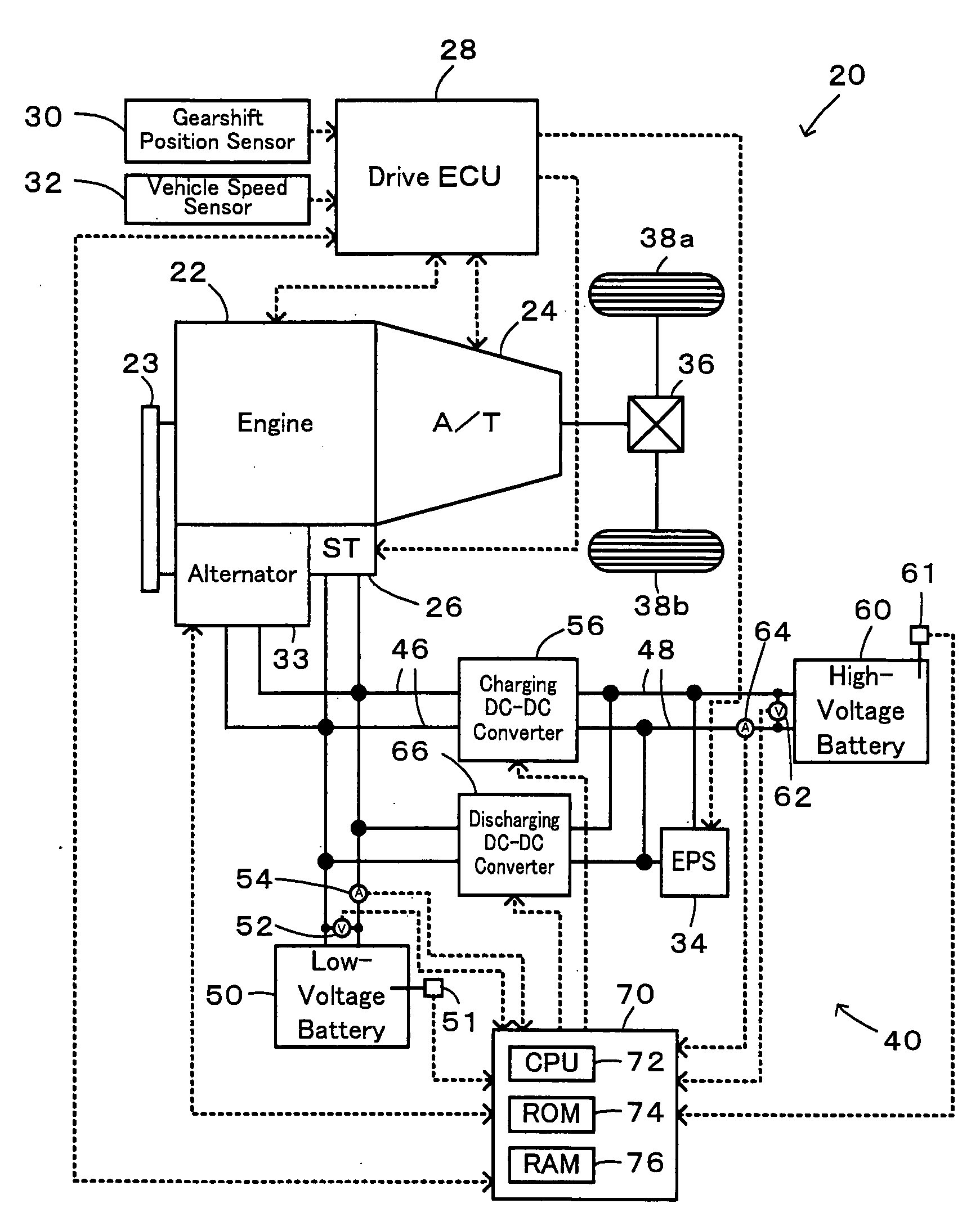
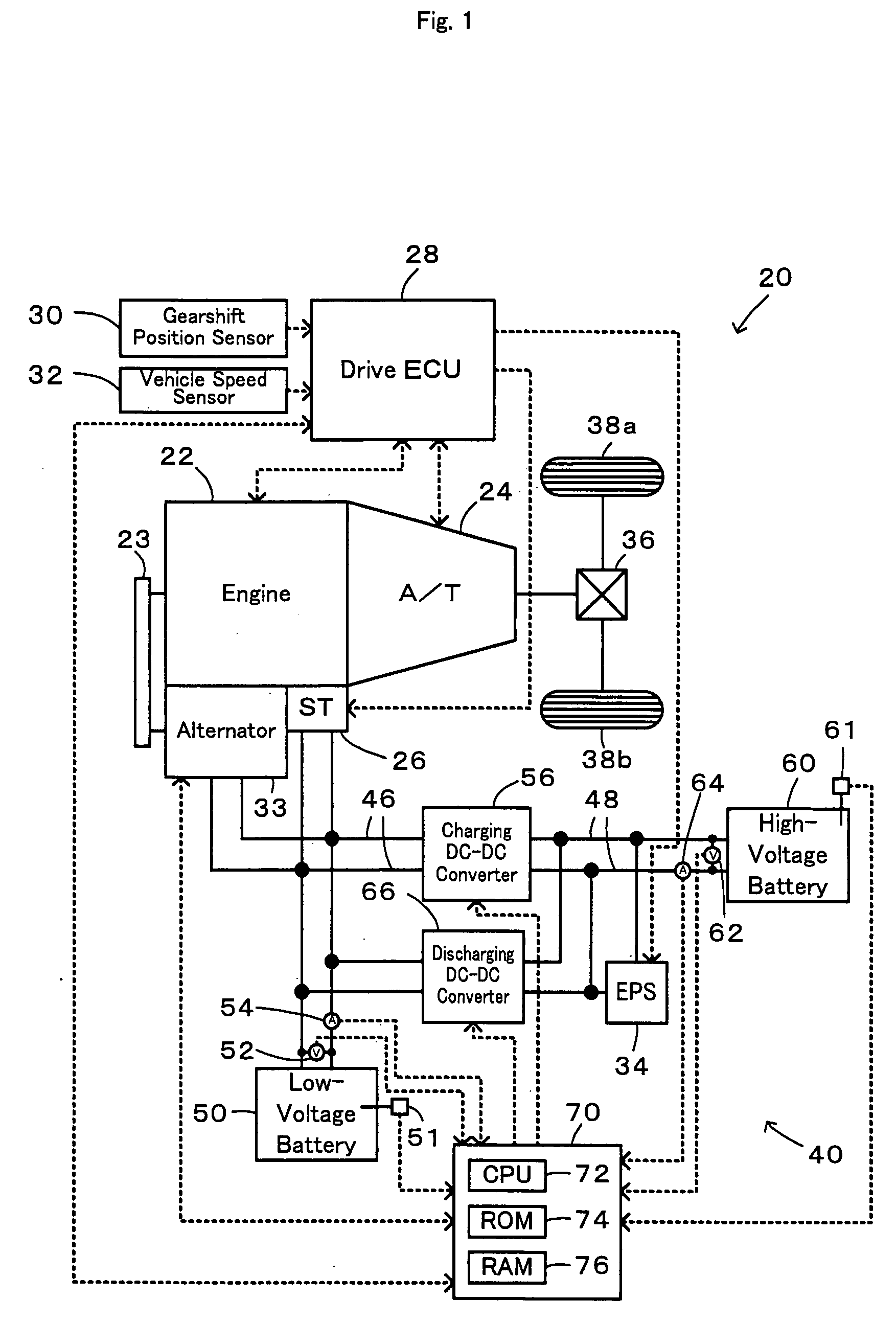
[0024]One mode of carrying out the invention is discussed below as a preferred embodiment with reference to accompanied drawings. FIG. 1 schematically illustrates the configuration of a motor vehicle 20 equipped with a power supply device 40 in one embodiment of the invention. As illustrated in FIG. 1, the motor vehicle 20 of the embodiment includes an engine 22 that consumes gasoline as a fuel to output power, and an automatic transmission 24 that converts the output power of the engine 22 at one of multiple gear ratios and outputs the converted power to drive wheels 38a and 38b via a differential gear 36. The motor vehicle 20 of the embodiment also has a drive electronic control unit 28 (drive ECU 28) that controls the operations of the engine 22 and the automatic transmission 24, an alternator 33 that has a rotating shaft connected to a crankshaft of the engine 22 via a belt 23 and consumes the output power of the engine 22 to generate electric power, and the power supply device ...


PUM

PropertyMeasurementUnit
rated output voltageaaaaaaaaaa
electric poweraaaaaaaaaa

Abstract

In a power supply device of the invention, when the state of charge SOC1 of a low-voltage battery is lower than a discharging reference value Shi1 below a full charge level and when the state of charge SOC2 of a high-voltage battery is not lower than a discharging reference value Slow2 at a system-off time, the low-voltage battery is charged close to its full charge level with the electric power supplied from the high-voltage battery. The lead acid battery used for the low-voltage battery has the high potential for deterioration in the continuously low state of charge SOC. The lithium secondary battery used for the high-voltage battery has the high potential for deterioration in the continuously high state of charge SOC. The charge of the low-voltage battery in combination with the discharge of the high-voltage battery enables both the low-voltage battery and the high-voltage battery to have respective favorable states of charge with little potentials for deterioration. The technique of the invention thus effectively prevents quick deterioration of both the low-voltage battery and the high-voltage battery.

Description

TECHNICAL FIELD[0001]The present invention relates to a power supply device, a control method of the power supply device, and a motor vehicle equipped with the power supply device. More specifically the invention pertains to a power supply device that receives an external supply of electric power and supplies electric power to an external electric power-consuming apparatus, a control method of such a power supply device, and a motor vehicle equipped with such a power supply device.BACKGROUND ART[0002]One proposed power supply device determines a voltage adjustment condition of plural cells, which are arranged in series to construct a battery assembly, according to the charge levels or the states of charge SOC of the respective cells, and actually adjusts the voltages of the respective cells in the battery assembly on the basis of the determined voltage adjustment condition (see, for example, Japanese Patent Laid-Open Gazette No. 2004-31012). Such voltage adjustment equalizes the vol...

Claims


Application Information

Patent Timeline
Patent Type & Authority Applications(United States)
IPC IPC(8): H02J7/00B60R16/03B60R16/033B60R16/04H01M10/44H01M10/48H02J7/34
CPCB60K6/28Y02T10/70B60L3/0092B60L11/14B60L11/1861B60L11/1868B60W10/08B60W10/26B60W20/00H02J7/0075Y02T10/7005Y02T10/7011Y02T10/7016Y02T10/7044Y02T10/7066Y02T10/7077B60Y2400/112B60L3/0046B60L50/16B60L58/12B60L58/20H02J7/0069Y02T10/7072B60W2510/244B60W2710/244
Inventor ESAKA, TOSHINORIOKABE, NOBUYUKIKOMEDA, OSAMU
Owner TOYOTA JIDOSHA KK
Why Eureka
Try Eureka