Cones and Cylinders of Laser Light

a laser light and cone technology, applied in waveguides, instruments, fibre light guides, etc., can solve the problems of objectionable changes in the light plane and thus the cylinder of light, system demands relatively stringent alignment and complexity, etc., to achieve economic manufacturing, the effect of alleviating complex manufacturing and operational requirements

Inactive Publication Date: 2006-07-27
TABOADA JOHN MARTIN +1
View PDF10 Cites 2 Cited by
  • Summary
  • Abstract
  • Description
  • Claims
  • Application Information

AI Technical Summary

Benefits of technology

[0008] Embodiments of the invention may be implemented to realize one or more of the following technical advantages of the invention. The laser projection technique directly converts a beam of laser light (or other electromagnetic radiation such as UV, visible, IR or microwave radiation) into a conical shell of light. The laser cone projection system can be economically manufactured to alleviate complex manufacturing and operational requirements. In one application, the laser cone projection technique can be used as a reference marker in industrial applications to assist in joining a cylindrical element to another element.

Problems solved by technology

Such a system demands relatively stringent alignment and complexity.
A change of 1 arc second in the incident angle of the laser beam can cause an objectionable change in the light plane and thus to the cylinder of light.

Method used


Image

  • Cones and Cylinders of Laser Light
  • Cones and Cylinders of Laser Light
  • Cones and Cylinders of Laser Light

Examples


Embodiment Construction

[0014] This Detailed Description describes an exemplary embodiment of the conical shell of radiation projection system used to convert a laser beam into a projected conical shell of laser light. The term “conical shell” is used to refer to a conical shell of any form of collimated electromagnetic radiation (i.e., a “shell of radiation”), including visible laser light, but also including non-visible electromagnetic radiation (such as UV, infrared, millimeter wave, and microwave).

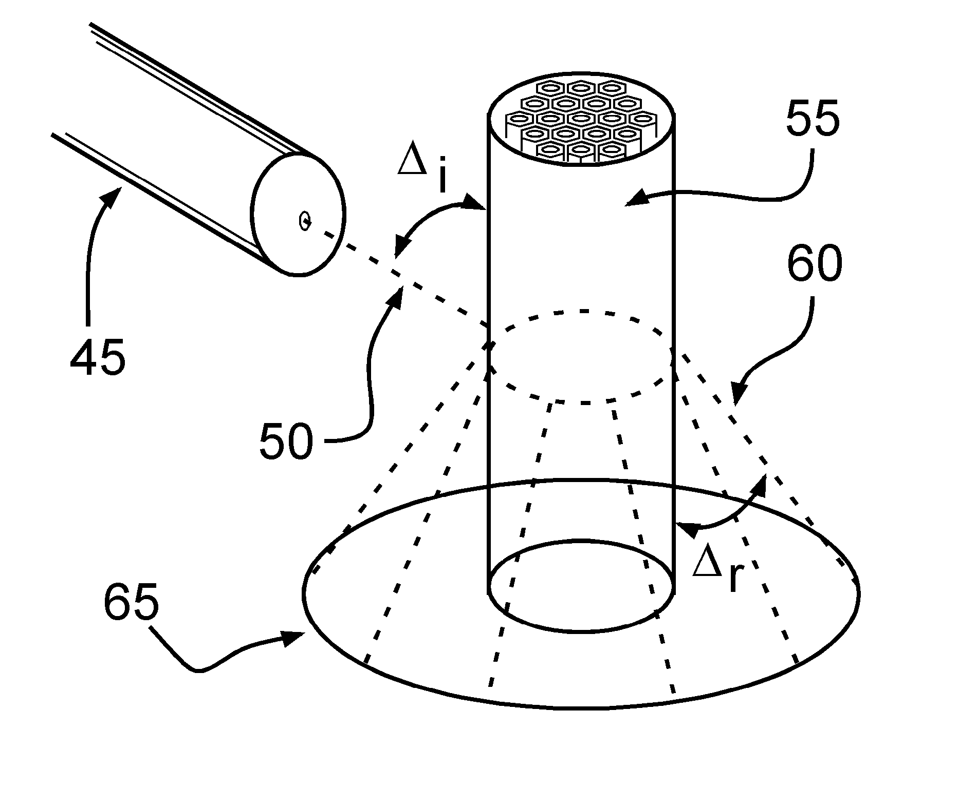
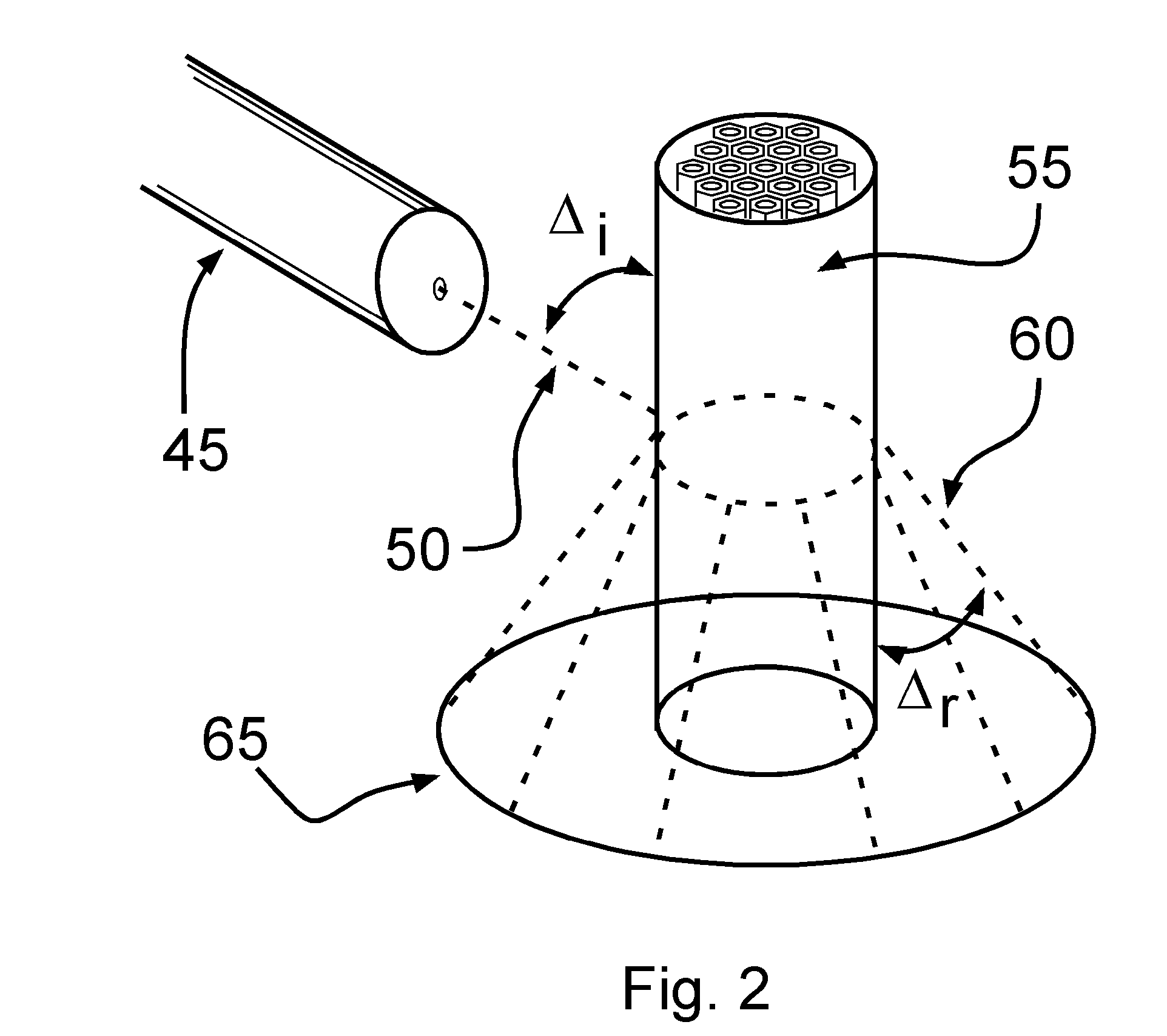
[0015] The exemplary laser conical shell projection system involves directing a laser beam non-orthogonal to a fiber-optic bundle, i.e., a fused bundle of individual fiber optic filaments. The incident laser light is projected conically outward from the fiber optic bundle forming a laser light conical shell. The longitudinal axis of the fiber optic bundle is the axis of the resulting conical laser light shell.

[0016]FIG. 2 illustrates the laser conical shell projection technique, projecting a laser conical s...


PUM


Abstract

A cone-of-light projection system projects a shell of laser light (or other electromagnetic radiation) using a fiber-optic bundle. Incidence optics directs a laser beam to be incident to the fiber-optic bundle at a predetermined angle of incidence, resulting in the projection of a conical shell of light. For the exemplary embodiment, the angle of incidence is non-orthogonal to the fiber-optic bundle, resulting in the projection of a conical shell of light. Thus, the laser projection technique converts a beam of laser light (or other electromagnetic radiation such as UV, visible, IR or microwave radiation) into a conically extending shell of light that in the exemplary embodiment is substantially conical. In one application, the laser projection technique can be used in industrial applications to assist in joining a cylindrical element to another surface.

Description

FIELD OF THE INVENTION [0001] The present invention relates to alignment and reference equipment, particularly to methods and apparatus for generating cones and cylinders of laser light. DESCRIPTION OF THE RELATED ART [0002] In many industrial applications, cylindrical or conical components are joined to other components. Having a simple, accurate, cost-effective, and easy-to-use apparatus would be helpful in combining such components. Laser light cones and cylinders are useful in projecting a pattern of the cylindrical or conical components and using the laser light as a template for joining the components. [0003] Without limiting the scope of the invention, the background information is provided in the context of a specific problem to which the invention has application: projecting a laser reference cone or cylinder with a minimum of moving parts and critical adjustments. [0004] Existing layout, measurement, and projection laser instruments, such as that shown in U.S. Pat. No. 6,7...

Claims


Application Information

Patent Timeline
Patent Type & Authority Applications(United States)
IPC IPC(8): G02B6/04G02B6/06
CPCG02B6/06Y10S385/901
Inventor TABOADA, JOHN MARTINTABOADA, JOHN
Owner TABOADA JOHN MARTIN
Why Eureka
Try Eureka