Method and apparatus for manufacturing three-dimensional objects

a three-dimensional object and manufacturing method technology, applied in the direction of additive manufacturing, process efficiency improvement, additive manufacturing apparatus, etc., can solve the problems of requiring additional processing time and cost for the removal step, and the outer surface of the three-dimensional object may not be smooth and accurate, so as to prevent unnecessary powder particle deposition, reduce the effect of forming accuracy and intensive heat of the target powder particl

Inactive Publication Date: 2006-07-27
AISAN IND CO LTD
View PDF4 Cites 70 Cited by
  • Summary
  • Abstract
  • Description
  • Claims
  • Application Information

AI Technical Summary

Benefits of technology

[0014] The “high-density energy heat source” used in the present invention refers to a heat source for locally heating a supplied powder area. For example, a plasma-transferred arc, a non-transferred plasma arc, a laser, or a mixture of these high-density energy heat sources may be used as the high-density energy heat source. In particular, the laser may include a carbon dioxide laser and a YAG laser. Such a heat source may be appropriately selected according to factors such as the type, the volume, and the particle diameters of the powder particles, and the accuracy requirements for forming the surface of the three-dimensional object. Using such a local heating heat source enables the target powder particles supplied onto a predetermined area to be intensively heated and sintered. Also, it is possible to prevent various defects such as lower forming accuracy and deposition of the powder particles onto the surface portions, otherwise caused by heat transferred to a

Problems solved by technology

In this case, the adhered powder forms a low-density surface layer so that the resulting three-dimensional object may not have a smooth and accurate outer surface.
However, according to this method, it wil

Method used


Image

  • Method and apparatus for manufacturing three-dimensional objects
  • Method and apparatus for manufacturing three-dimensional objects

Examples


example

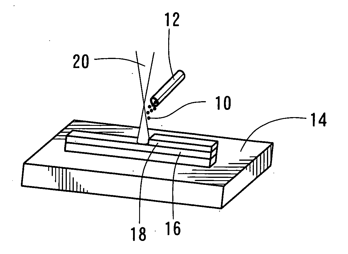
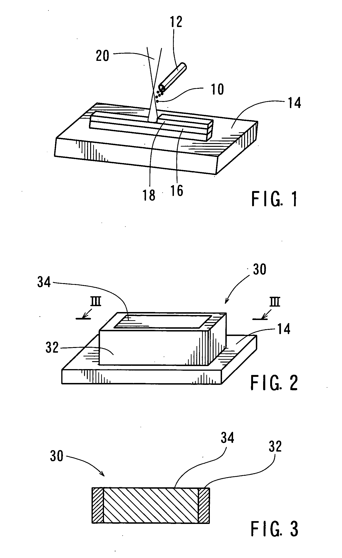
[0055] A more specific embodiment of the present invention will be described below. In this representative embodiment, a Model PF-01 disc-type powder feeder, available from Nihon Welding Rod Co., Ltd., Japan, was used as the powder particle supplying device. A Model 2012H CO2 laser having a 50C oscillator, a rated power of 5 kW, and an argon shielding gas, available from Mitsubishi Electric Corporation, Japan, was used as the high-density energy heat source. Further, two types of powder particles, as shown in Table 1, are used as the powder particles in this representative embodiment.

TABLE 1Details of Powder ParticlesNo.Type of Powder ParticlesMaterialAverage Particle Diameter1Spherical PowderSUS420 30 μm2Granulated PowderSUS410L200 μm (Granulated from10 μm Powder Particles)

[0056] As shown in FIG. 2, by using the aforementioned devices, a three-dimensional object 30 having an outside dimension of 100 mm×100 mm×100 mm was manufactured. As shown in Table 1, with respect to the surfa...


PUM

PropertyMeasurementUnit
Densityaaaaaaaaaa
Particle diameteraaaaaaaaaa

Abstract

The present invention teaches a method and an apparatus for manufacturing a three-dimensional object having a smooth outer surface, without any step of removing a surface layer each time a sintered layer is formed so as to manufacture a three-dimensional object consisting of integrally built-up sintered layers. The method may include the steps of: (i) supplying powder particles (10) onto a moving area while heating the powder particles (10) with heat (20) from a high-density energy heat source so as to form a sintered layer (16); and (ii) supplying powder particles 10 onto a moving area on the sintered layer while heating the powder particles (10) with heat (20) from the high-density energy heat source so as to form another sintered layer (18) integrally on the sintered layer (16), wherein the step (ii) is repeated a predetermined number of times.

Description

[0001] This application claims priority to Japanese patent application serial number 2005-15483, the contents of which are incorporated herein by reference. BACKGROUND OF THE INVENTION [0002] 1. Technical Field [0003] The present invention relates to a method and an apparatus for manufacturing three-dimensional objects consisting of integrally built-up sintered layers. [0004] 2. Description of the Related Art [0005] In order to manufacture three-dimensional objects consisting of integrally built-up sintered layers, Japanese Laid-Open Publication Nos. 2002-115004 and 2003-159755 disclose a rapid prototyping method including the steps of: forming a powder layer of inorganic or organic material on a sintering table; sintering a predetermined portion of the powder layer by irradiating with an optical beam to form a sintered layer; covering the sintered layer with a new powder layer; and repeating the aforementioned steps to form a plurality of sintered layers united together. [0006] Acc...

Claims


Application Information

Patent Timeline
IPC IPC(8): B22F7/02
CPCB22F3/1055B22F2003/1056B33Y30/00B33Y10/00Y02P10/25B22F10/10B22F12/33B22F10/25B22F12/53B22F12/224
Inventor YAMADA, SHIGEKIHARA, HIROYUKI
Owner AISAN IND CO LTD
Why Eureka
Try Eureka