Valve and retainer assembly for latex balloons

a technology which is applied in the field of valve and retainer assembly of balloons, can solve the problems of balloon special order, high cost, and high cost, and achieve the effect of increasing the speed of balloon-within-balloon

Inactive Publication Date: 2006-07-27
PREMIUM BALLOON ACCESSORIES
View PDF30 Cites 5 Cited by
  • Summary
  • Abstract
  • Description
  • Claims
  • Application Information

AI Technical Summary

Benefits of technology

[0010] To use the valve and retainer assembly, the mouth of a first balloon, which is typically defined by a rolled portion of balloon material, is stretched over the perimeter of the radial shoulder. Then the mouth of a second balloon is stretched over the perimeter of the slide disk such that the first balloon is located inside of the second balloon. The slide disk is moved along the stem portion so that its seal sleeve does not cover the at least one second balloon fill aperture in the stem portion, and the at least one second balloon fill aperture communicates with the interior of the second balloon. Gas, typically helium, is forced through the hollow of the stem portion and enters the second balloon by way of the at least one second balloon fill aperture. The configuration of the valve and retainer assembly is such that, when the at least one second balloon fill aperture is uncovered, gas introduced through the hollow of the stem portion exits the hollow at the at least one second balloon fill aperture, as this is the path of least resistance for the gas. The gas does not force the band valve off of the at least one first balloon fill aperture in the fill portion. After the second, exterior balloon is filled to a desired extent, the slide disk is moved so that its seal sleeve covers the at least one second balloon fill aperture in the stem portion, and, thereafter, gas introduced to the hollow of the stem portion pushes against the band valve through the at least one first balloon fill aperture, causing the band valve to flex to allow gas to flow from the hollow of the stem portion, through the at least one first balloon fill aperture, to fill the first balloon inside of the second balloon. Thus, the slide disk acts as a valve that can be selectively manipulated to cover or uncover the at least one second balloon fill aperture to have it selectively communicate with the interior of the second exterior balloon. This valve assembly significantly increases the speed at which balloon-within-balloon displays might be filled from a pressurized gas source and, thereafter, employed to decorate a particular event.

Problems solved by technology

In such cases, the balloons are special ordered, at significant expense.
Decorating the event may also entail a significant expense inasmuch as a great amount of time and effort is required to fill these latex balloons and affix them to ribbons or balloon sticks, for display at the event.
The prior art valve and retainer assemblies, however, are quite complex, and are undesirably difficult to manufacture, assemble, and use.
It has also been found that some valve designs suffer from creating too much noise during inflation of a balloon.
Decorating an event with such displays may also entail a significant expense inasmuch as a great amount of time and effort is required to fill the balloon-within-balloon displays and affix them to ribbons or balloon sticks, for display at the event.

Method used


Image

  • Valve and retainer assembly for latex balloons
  • Valve and retainer assembly for latex balloons
  • Valve and retainer assembly for latex balloons

Examples


Embodiment Construction

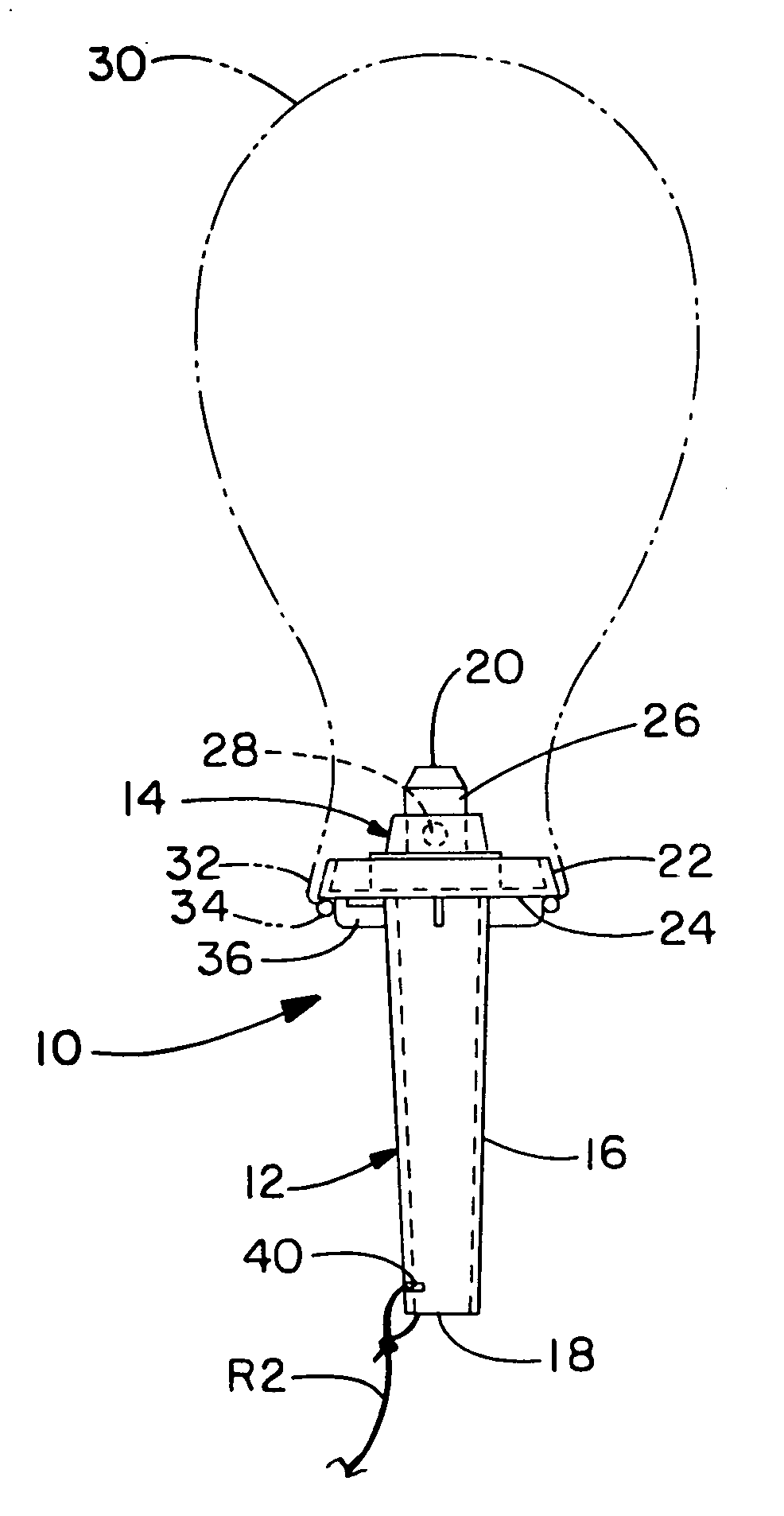
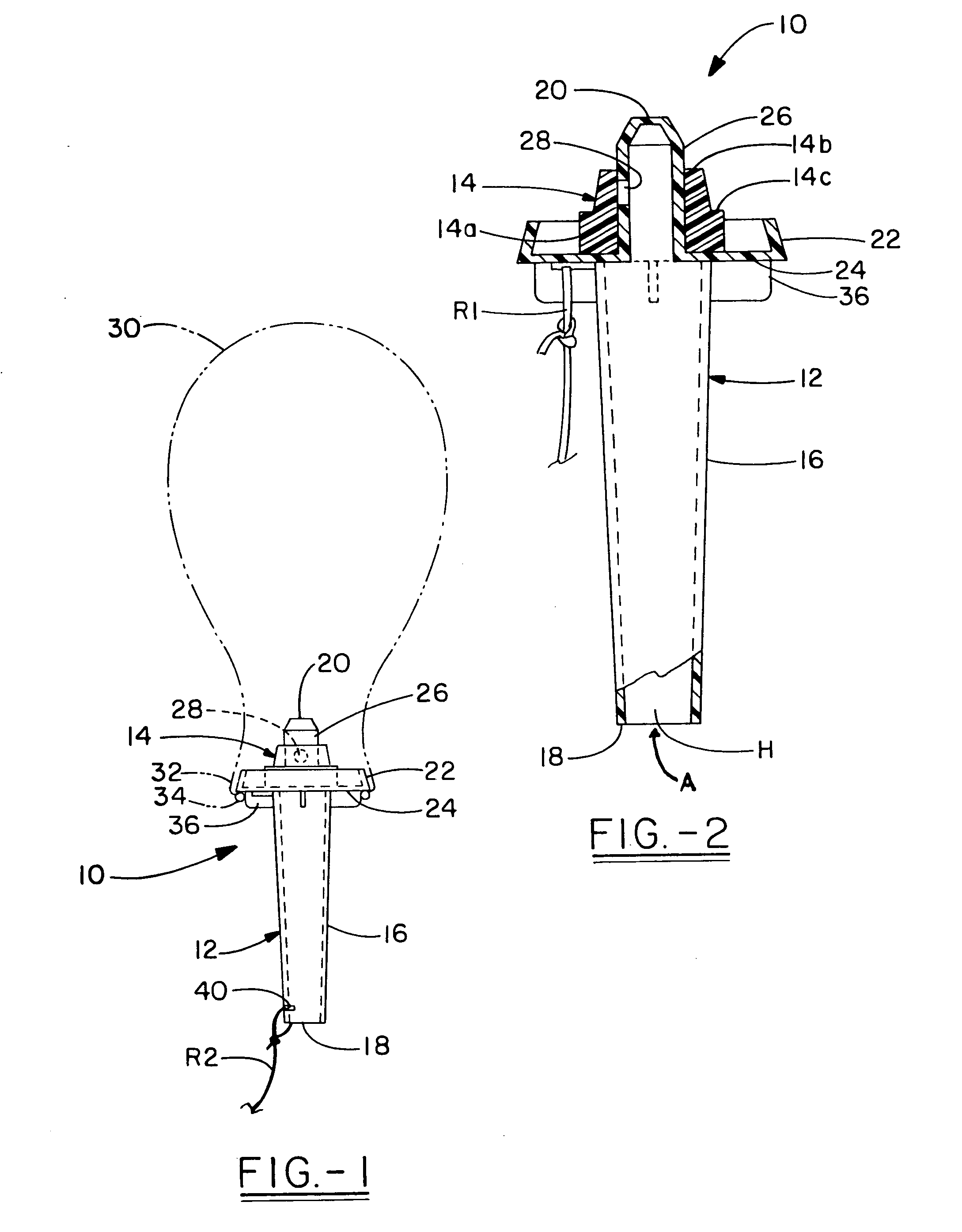
[0016] With reference to FIG. 1-2, it can be seen that a valve and retainer assembly according to this invention is designated generally by the numeral 10. Valve and retainer assembly 10 includes valve body 12, which, as will be described below, receives band valve 14. Valve body 12 includes stem 16, which is hollow as represented by the letter H in FIG. 2, from first end 18 to closed second end 20. Valve body 12 further includes retainer portion 22 that extends outwardly from stem 16. Retainer portion 22 includes radial shoulder 24, which extends radially outwardly from a position recessed from closed second end 20 of stem 16, thereby defining fill portion 26 of stem 16 as the portion of stem 16 that extends beyond radial shoulder 24 to closed second end 20. Although this invention is not to be so limited, it is preferred that valve body 12, including stem 16 and radial shoulder 24, be molded as a single component. Additionally, it is preferred that radial shoulder 24 be circular i...


PUM


Abstract

A valve and retainer assembly particularly useful for latex balloons includes a valve body and a band valve. The valve body has a radial shoulder where the neck and mouth of a latex balloon may be received to affix the balloon to the valve body. A hollow stem communicates with the radial shoulder, and a one-way valve allows gas to be introduced through the stem into the balloon affixed to the retainer portion. A valve and retainer for filling first and second balloons further includes a slide disk having a seal sleeve that intimately fits over the stem portion, such that the sealing slide disk selectively slides along the stem portion so that the seal sleeve can selectively cover the at least one second balloon fill aperture; and a flexible band covering the at least one fill aperture of the fill portion.

Description

BACKGROUND OF THE INVENTION [0001] The present invention generally resides in the art of balloon devices and accessories. More particularly, the present invention relates to a valve and retainer assembly for a latex balloon, and its method of use. [0002] The use of latex balloons as decorations for parties, celebrations, grand openings, and other events is well known, and millions of balloons are so used each year. At many of these events, a substantially large number of latex balloons are decoratively employed, and, many times, the latex balloons are printed with indicia that is particular to the specific event. In such cases, the balloons are special ordered, at significant expense. Decorating the event may also entail a significant expense inasmuch as a great amount of time and effort is required to fill these latex balloons and affix them to ribbons or balloon sticks, for display at the event. Thus, manufacturers involved with providing such balloons have endeavored to provide l...

Claims


Application Information

Patent Timeline
Patent Type & Authority Applications(United States)
IPC IPC(8): A63H3/06
CPCA63H27/10A63H2027/1083F16K15/142
Inventor NELSON, DAVID C.MELUCH, MARTIN A.
Owner PREMIUM BALLOON ACCESSORIES
Why Eureka
Try Eureka