Ice auger cordless drill adaptor

a cordless, ice auger technology, applied in the field of ice auger adaptors, can solve the problems of ice auger falling through the hole into the water, all prior art devices described above suffer from certain disadvantages, and the drilling process is laborious and time-consuming, so as to prevent unintended detachment, prevent damage to the drill chuck, and stabilize the whole apparatus

Inactive Publication Date: 2006-08-03
KOWALEWSKI TRACY ALAN
View PDF8 Cites 12 Cited by
  • Summary
  • Abstract
  • Description
  • Claims
  • Application Information

AI Technical Summary

Benefits of technology

[0010] Thus, when the retaining cord is wrapped around the drill and its ends secured, it holds the retainer firmly and snugly onto the connecting pin with the connecting pin free to rotate within the retainer as it is driven by the power drill. Hence, the ice auger which is connected to its second end will also rotate while the retaining disc is held stationary with respect to the power drill. Furthermore, the retainer and the retaining cord serve to secure the connecting pin and ice auger to

Problems solved by technology

However, while such augers can be operated by hand, hand drilling the hole through the ice is a laborious and time-consuming process.
However, many of these known devices suffer from the problem that the auger can detach from the drill when it is in operation, thus resulting in the ice auger falling through the hole into the water.
However, all of the prior art devices described above suffer from certain disadvantages.
When they are in use, the chuck of the drill must bear the entire weight of the ice auger (plus whatever adaptor is in use), which oft

Method used


Image

  • Ice auger cordless drill adaptor
  • Ice auger cordless drill adaptor
  • Ice auger cordless drill adaptor

Examples


Embodiment Construction

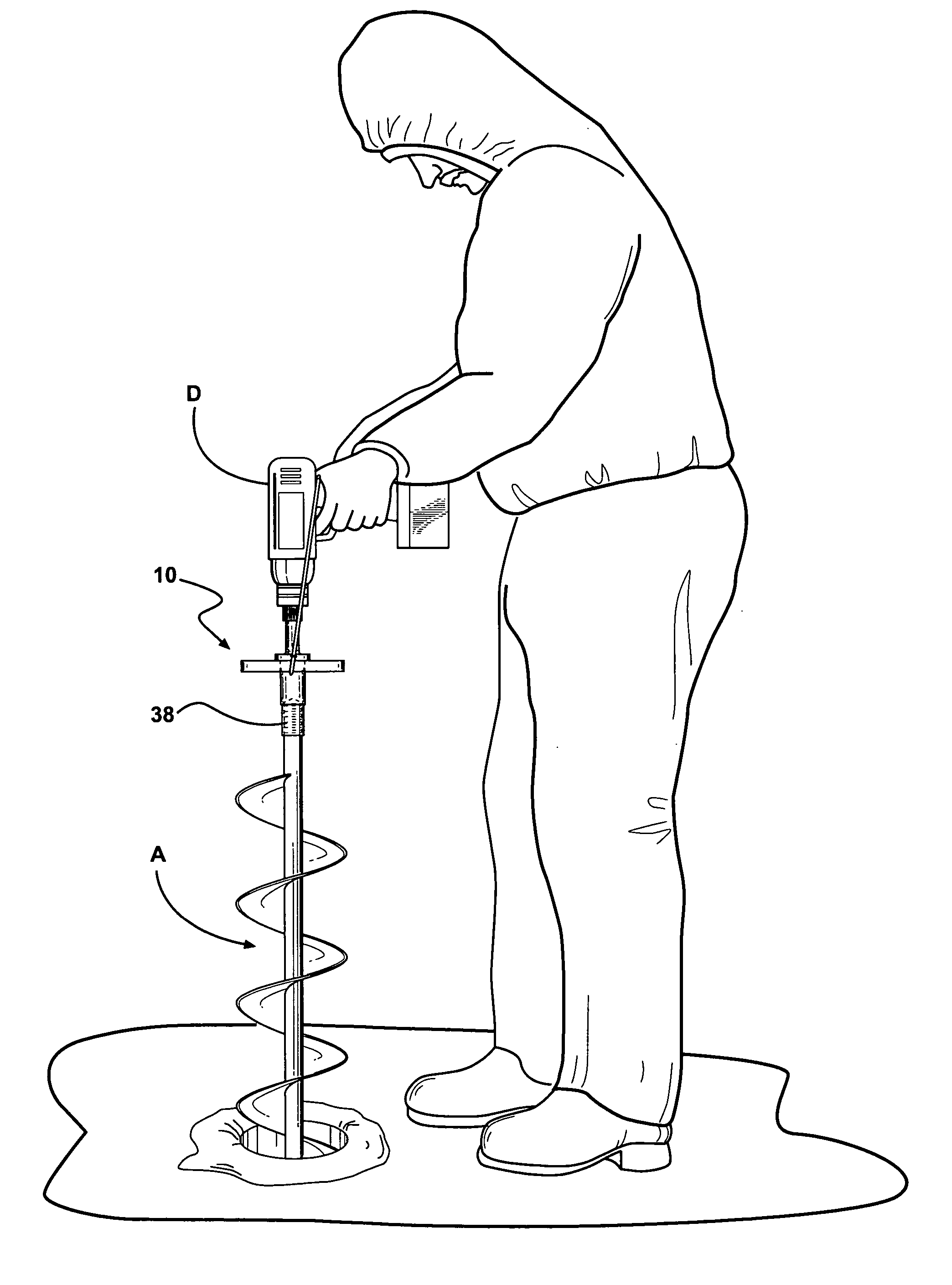
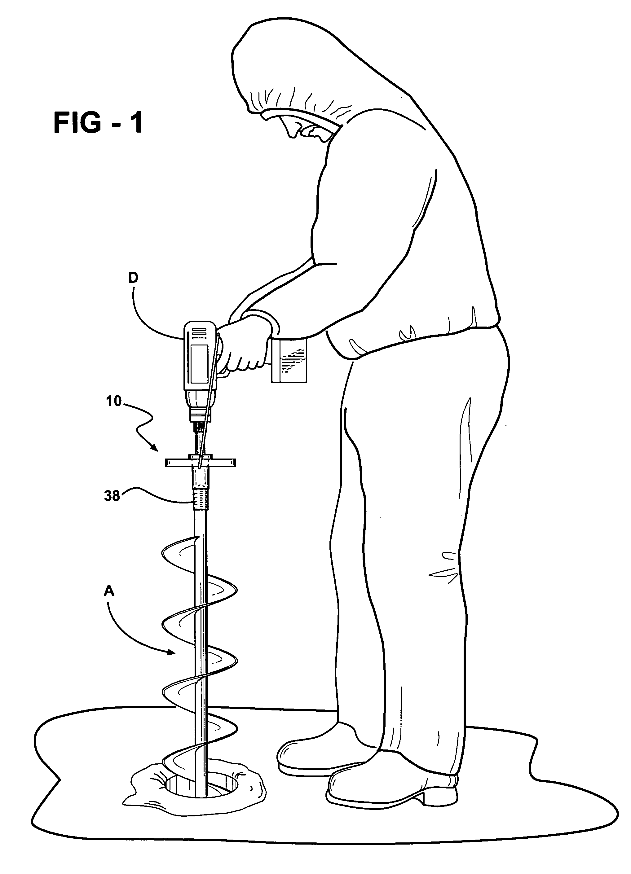
[0020] Throughout the following detailed description, like reference numerals are used to refer to the same element of the herein invention shown in multiple figures thereof. Referring now in particular to FIGS. 1, 2 and 3, there is shown an ice auger adaptor 10 which includes a connection pin 16. Attached to a first end 12 of the connection pin 16 is a conventional cordless power drill D of the type which is most typically battery powered. Attached to the second end 14 is a conventional hand ice auger A.

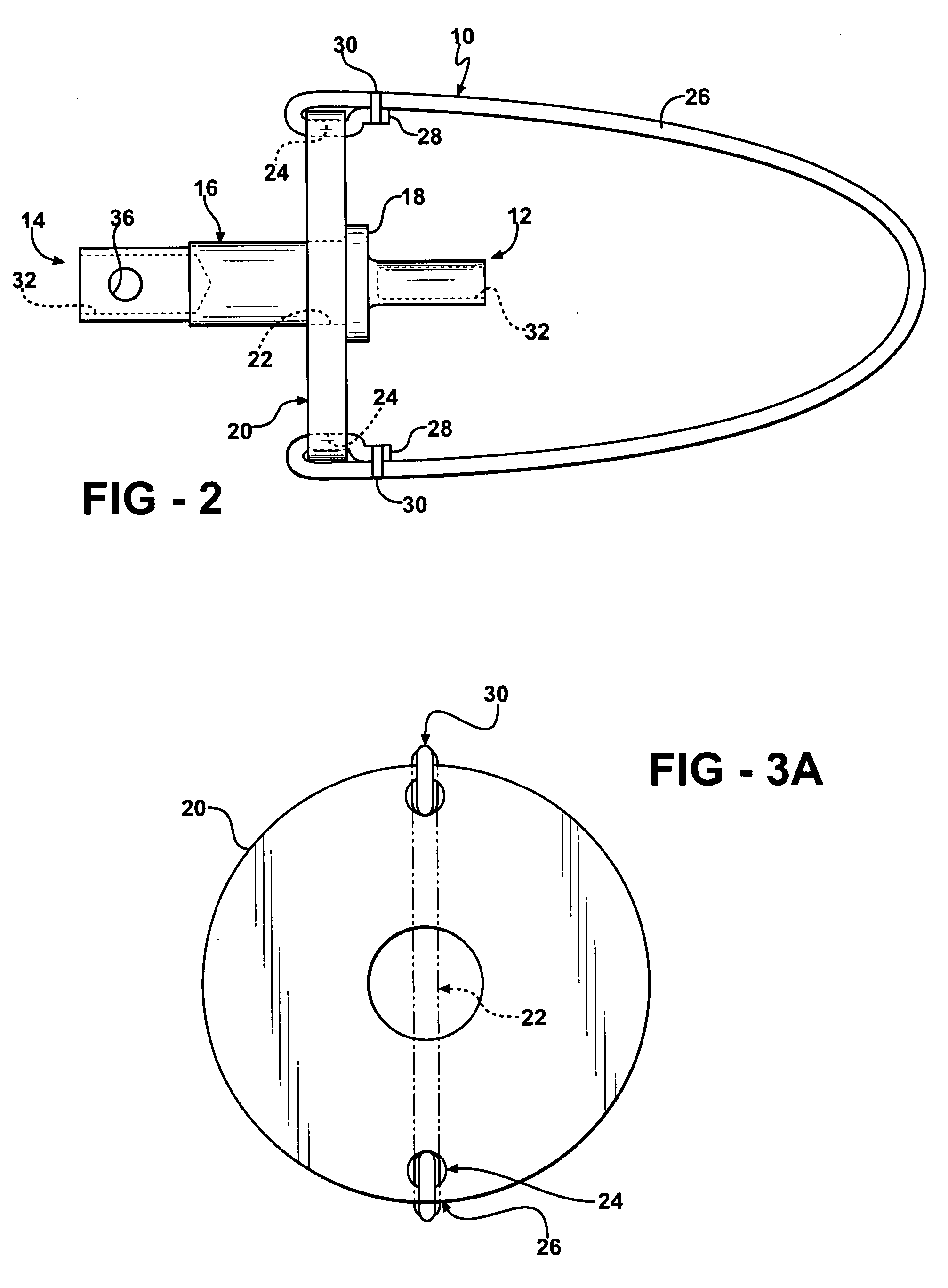
[0021] In the side view of FIG. 2, more details of the present invention can be discerned. A connection pin 16 has a first end 12 adapted to attach to the chuck of a drill and second end 14 adapted to attach to the shaft of an ice auger. A flange 18 is disposed around the body of the connection pin 16 at a location which is between the two ends and, in the embodiment shown in FIG. 2, proximate the first end 12. Connection pin 16 has a retainer 20 (best seen in FIG. 3) installed ont...


PUM


Abstract

An ice auger adaptor for connecting a portable drill to an ice auger. The adaptor includes a connecting pin having a first end for connection to the chuck of a power drill and a second end configured to install on the shaft of an ice auger. Disposed on the connection pin between the two ends and proximate the first end is a flange. A retaining disc having a center aperture is installed on the connection pin so that it abuts against the flange. The center aperture has a diameter sufficiently larger than the diameter of the connection pin to permit free rotational movement therebetween. The retaining disc also includes two peripheral apertures which can be connected to the ends of an elastomeric retaining cord. The retaining cord has a length such that, when it is wrapped around the body of the drill, the retaining disc and remainder of the adaptor are secured snugly to the drill. The retaining disc and retaining cord cooperate to keep the ice auger secured to the drill and prevent accidental falls of the ice auger through the ice. They also serve to support much of the weight of the drill lid, thus preventing damage to the chuck.

Description

REFERENCE TO RELATED APPLICATION [0001] This application is based on and claims priority from U.S. provisional patent application 60 / 647,933, filed Jan. 31, 2005.FIELD OF THE INVENTION [0002] This invention relates to the field of ice auger adaptors, and specifically to ice auger adaptors which safely and securely connect a portable power drill to an ice auger. BACKGROUND OF THE INVENTION [0003] In order to engage in the popular winter pastime of ice fishing, it is first necessary to make a hole in the ice so that the fisherman can access the open water lying therebelow. Ice augers, which are designed to bore a hole through the ice to permit such access, are in common use. However, while such augers can be operated by hand, hand drilling the hole through the ice is a laborious and time-consuming process. [0004] Hence, a variety of methods are commonly used to power the ice auger. For example, U.S. Pat. No. 4,971,161 discloses an ice auger conversion kit which can be mounted to a con...

Claims


Application Information

Patent Timeline
IPC IPC(8): F25C5/04
CPCA01K97/01E21B7/008F25C5/04
Inventor KOWALEWSKI, TRACY ALAN
Owner KOWALEWSKI TRACY ALAN
Why Eureka
Try Eureka