Drive system for motor vehicle

Inactive Publication Date: 2006-08-03
DANA AUTOMOTIVE SYST GRP LLC
View PDF5 Cites 17 Cited by
  • Summary
  • Abstract
  • Description
  • Claims
  • Application Information

AI Technical Summary

Problems solved by technology

Although open differentials may be adequate for most driving conditions, they are generally unsuitable for slippery conditions where one wheel experiences a much lower coefficient of friction than the other wheel.
If even a small amount of torque is directed to the wheel without traction, the torque will cause the wheel to “spin out”.
Sin

Method used


Image

  • Drive system for motor vehicle
  • Drive system for motor vehicle
  • Drive system for motor vehicle

Examples


Embodiment Construction

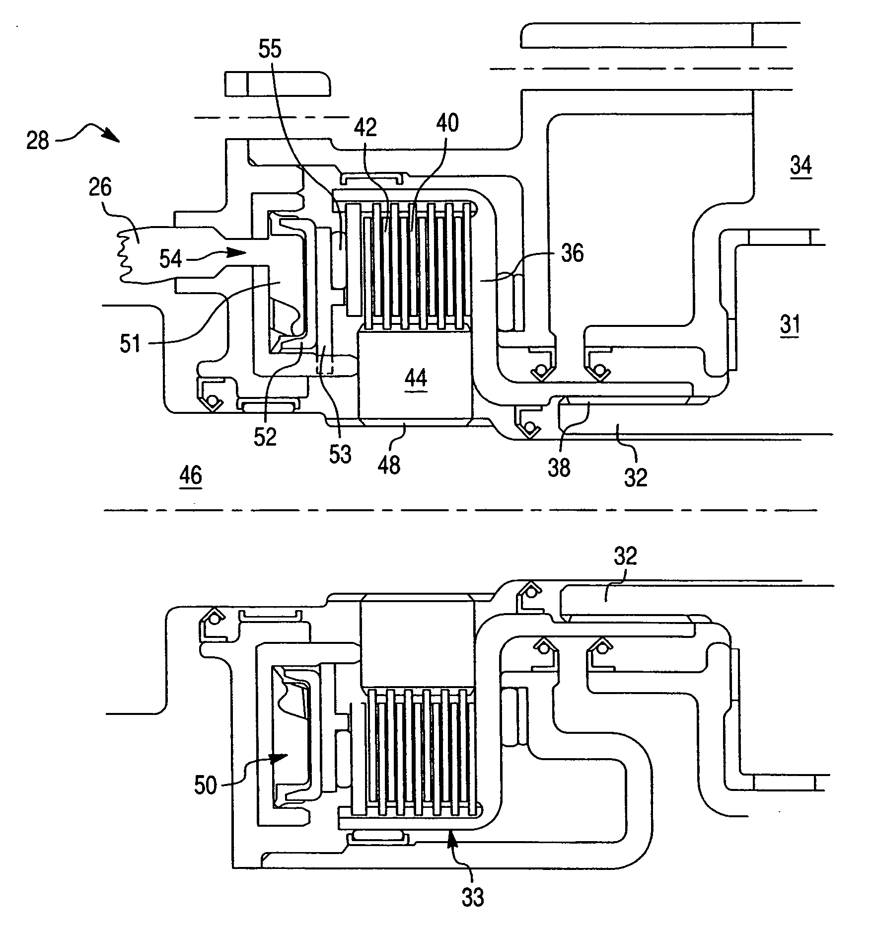
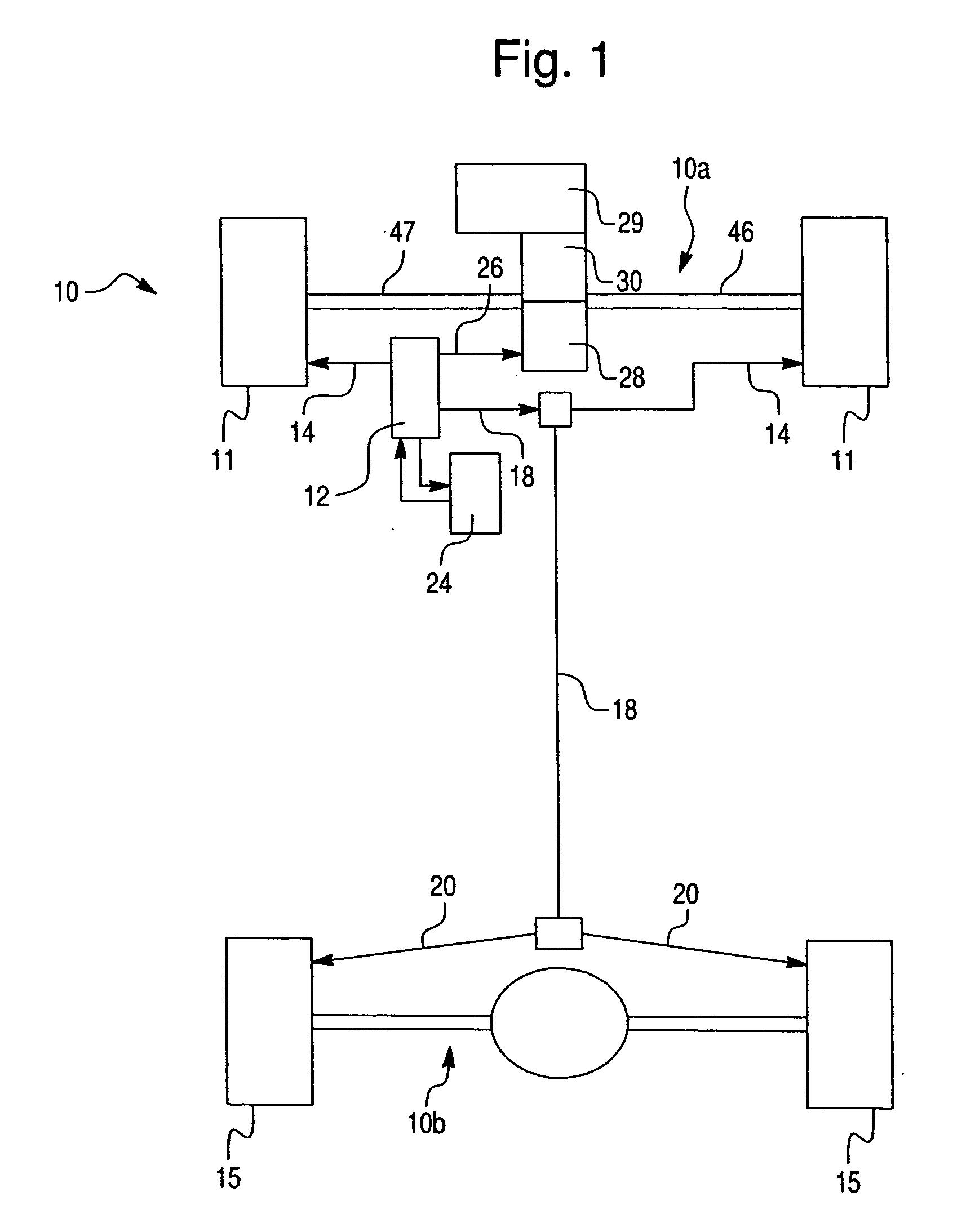
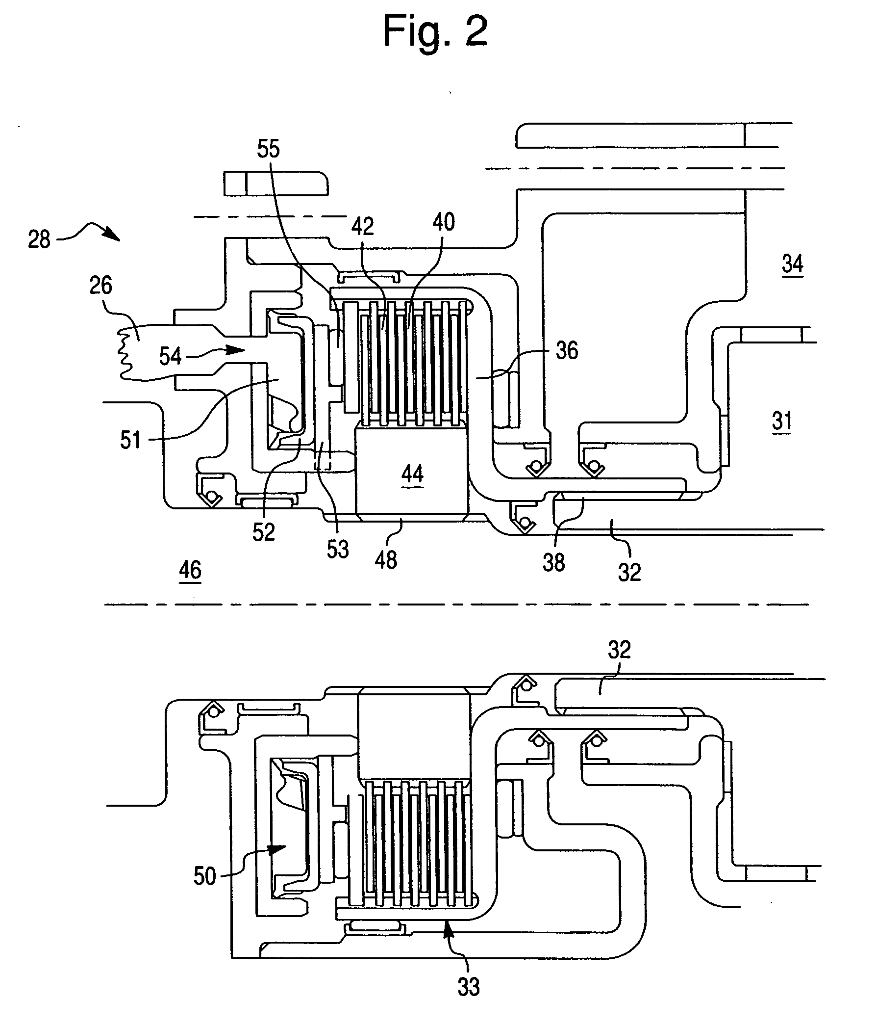
[0029] As best shown in FIG. 1, the first exemplary embodiment of the present invention comprises a drive system 10 that is integrated into an antilock brake system of a motor vehicle having a front axle 10a and a rear axle 10b. The antilock brake system comprises a hydraulic brake pump 12 which provides pressurized hydraulic fluid to the brake system. The brake system also includes front brake supply lines 14 supplying brake fluid to the front wheels 11, and intermediate 18 and rear 20 brake fluid supply lines supplying brake fluid to rear wheels 15. The antilock brake system is controlled by an antilock brake system control module 24.

[0030] As best shown in FIG. 1, the hydraulic brake pump 12 and the antilock brake system control module 24 are also components of the drive system. In the embodiment shown in FIG. 1, the hydraulic brake pump 12 supplies pressurized hydraulic fluid through a front differential supply line 26 to a front controllable limited slip differential assembly ...


PUM


Abstract

A drive system designed to use a vehicle's existing hydraulic system to operate a controllable limited slip differential assembly. The limited slip differential assembly may be associated with the front axle, the rear axle, or the driveline between the front and rear axles. The differential assembly may also be used in combination that includes front, rear, or intermediate differential assemblies. The drive system further includes a friction clutch assembly for selectively engaging and disengaging an input member with an output member of the differential assembly, a fluid clutch actuator for selectively frictionally and variably loading the clutch assembly, and a fluid pump that is a common source of pressurized fluid for the fluid clutch actuator and the existing hydraulic system of the motor vehicle other than the fluid clutch actuator of the drive system. The fluid clutch actuator is actuated by fluid pressure generated by the fluid pump.

Description

CROSS-REFERENCE TO RELATED APPLICATION [0001] This application is a continuation-in-part of pending application Ser. No. 11 / 048,047, filed on Feb. 2, 2005.BACKGROUND OF THE INVENTION [0002] 1. Field of the Invention [0003] The present invention relates to drive systems for motor vehicles in general, and more specifically, a vehicular drive system including a fluidly actuated friction clutch assembly actuated with a fluid pump integrated with one of hydraulic systems of the motor vehicle. [0004] 2. Description of Related Art [0005] Differential assemblies are arranged in the power transmission system of a motor vehicle to allow a pair of output shafts operatively coupled to an input shaft to rotate at different speeds, thereby allowing the wheel associated with each output shaft to maintain traction while the vehicle is turning. The differential distributes the torque provided by the input shaft between a first and second output shaft. The most basic and common type of differential i...

Claims


Application Information

Patent Timeline
IPC IPC(8): B60K23/04
CPCB60K17/3462B60K23/04B60K23/0808
Inventor KRISHER, JAMES A.COOPER, KENNETH E.NAHRWOLD, THOMAS L.HUNT, GORDON W.BAXTER, RALPH W. JR.SOMMER, RANDY
Owner DANA AUTOMOTIVE SYST GRP LLC
Why Eureka
Try Eureka