
Variable rectangle-type electron beam exposure apparatus and pattern exposure-formation method

an electron beam and exposure apparatus technology, applied in the direction of basic electric elements, electric discharge tubes, nanotechnology, etc., can solve the problems of inability to put the method into practical use, the difficulty of forming a servo information pattern with an exclusively used device, and the required exposure time for making the servo information pattern is extremely long

Inactive Publication Date: 2006-08-03
FUJITSU MICROELECTRONICS LTD
View PDF2 Cites 27 Cited by
  • Summary
  • Abstract
  • Description
  • Claims
  • Application Information

AI Technical Summary

Benefits of technology

[0017] In the above variable rectangle-type electron beam exposure apparatus and the pattern exposure and formation method, a plurality of apertures of different angles are provided in the first and the second slit member, and the exposure can be conducted by an electron beam passing through any one set of apertures. Therefore, it is possible to provide rectangular electron beams having various angles. That is, when the first exposure pattern of a predetermined angle is combined with the second exposure pattern of a different angle, it becomes possible to conduct the exposure on a pattern of a higher degree of freedom and on a region of a figure in a short period of time.
[0021] In the above variable rectangle-type electron beam exposure apparatus and the pattern exposure method, when the electron beams passing through the pentagonal apertures provided in the first and the second slit are appropriately combined with each other, the rectangular electron beams of different angles can be obtained. That is, when the first exposure pattern of a predetermined angle and the second exposure pattern of a different angle are combined with each other, the exposure can be conducted on a pattern of a higher degree of freedom or a region of a figure in a short period of time.
[0023] In the case where exposure is conducted by putting variable rectangle-type beams on each other at the exposure interval of 1 / N (N>1), for example, ½ pitch, when a beam irradiation of each beam is made to be smaller than each beam irradiation (dose) in the case of conducting exposure at the interval of one pitch, it is possible to prevent a swelling of the pattern at the edge portion of a pattern figure to be made. Therefore, it is possible to highly accurately make a pattern having a line width similar to an objective pattern figure.
[0025] When one redundant variable rectangle is generated which is put on the figure by ½ pitch so that the redundant variable rectangle can be located across the pattern figure to be made, a problem of the lack of accuracy at the connecting portion can be solved, and a pattern shape of this connecting portion can be made smooth.

Problems solved by technology

Therefore, in the case where servo information is written on the disk-shaped recording medium so that a magnetic head for reading and writing the signal information on the disk-shaped recording medium can be positioned with respect to the disk-shaped recording medium, it has become difficult to form a servo information pattern with an exclusively used device while the mechanical accuracy is kept high.
When a commonly used point beam type electron beam exposing apparatus, by which an arbitrary figure can be drawn, is used, in order to make a servo information pattern on the entire face of one piece of the disk-shaped recording medium, the diameter of which is 5 to 10 cm, by applying this technique, an extremely long exposure time is required for making the servo information pattern.
Therefore, this method can not be put into practical use.
However, in the case of the variable rectangle-type electron beam exposing machine shown in FIG. 15, the following problems may be encountered.
After all, in the same manner as the case of the point beam type electron beam exposure, a long exposure time is required.
However, with respect to a predetermined fine line pattern having an arbitrary angle, it is impossible to conduct a highly fine exposure in the pattern region.
In the case where the above conventional point beam type electron beam exposing machine is used, it takes an extremely long time for the exposing machine to expose and form the servo information pattern on the entire face of a piece of disk-shaped recording medium.
Therefore, it is difficult to put the conventional point beam type electron beam exposing machine into practical use.
However, especially when the pattern angle and the rectangular beam angle are different from each other at the edge portion of the pattern, it is impossible to conduct exposure with high accuracy.
However, this variable formation electron beam drawing apparatus is not suitable for the highly accurate exposure of a predetermined fine line pattern having an arbitrary angle in the pattern region.

Method used


Image

  • Variable rectangle-type electron beam exposure apparatus and pattern exposure-formation method
  • Variable rectangle-type electron beam exposure apparatus and pattern exposure-formation method
  • Variable rectangle-type electron beam exposure apparatus and pattern exposure-formation method

Examples


first embodiment

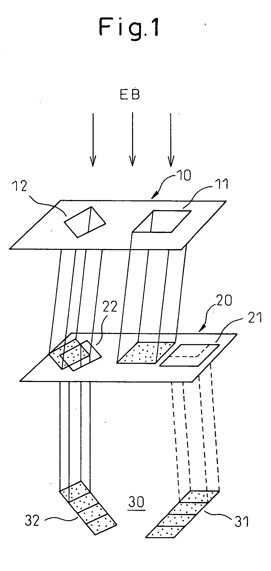
[0042]FIG. 1 is a perspective view showing the variable rectangle-type electron beam exposure apparatus of the present invention.

[0043] In the first slit member 10, which is formed into a flat-plate-shape, two apertures 11, 12 of the same size and shape are arranged and spaced from each other wherein these two apertures 11, 12 are directed in a different direction from each other by 45°. In the same manner, in the second slit member 20 (pattern block mask), which is formed into a flat-plate-shape, two apertures 21, 22 of the same size and shape are arranged and spaced from each other wherein these two apertures 21, 22 are directed in a different direction from each other by 45°. The first slit member 10 and the second slit member 20 are arranged in parallel with each other.

[0044] Each side of the first rectangular aperture 11 of the first slit member 10 is parallel with each side of the first rectangular aperture 21 of the second slit member 20. In the same manner, each side of the...

second embodiment

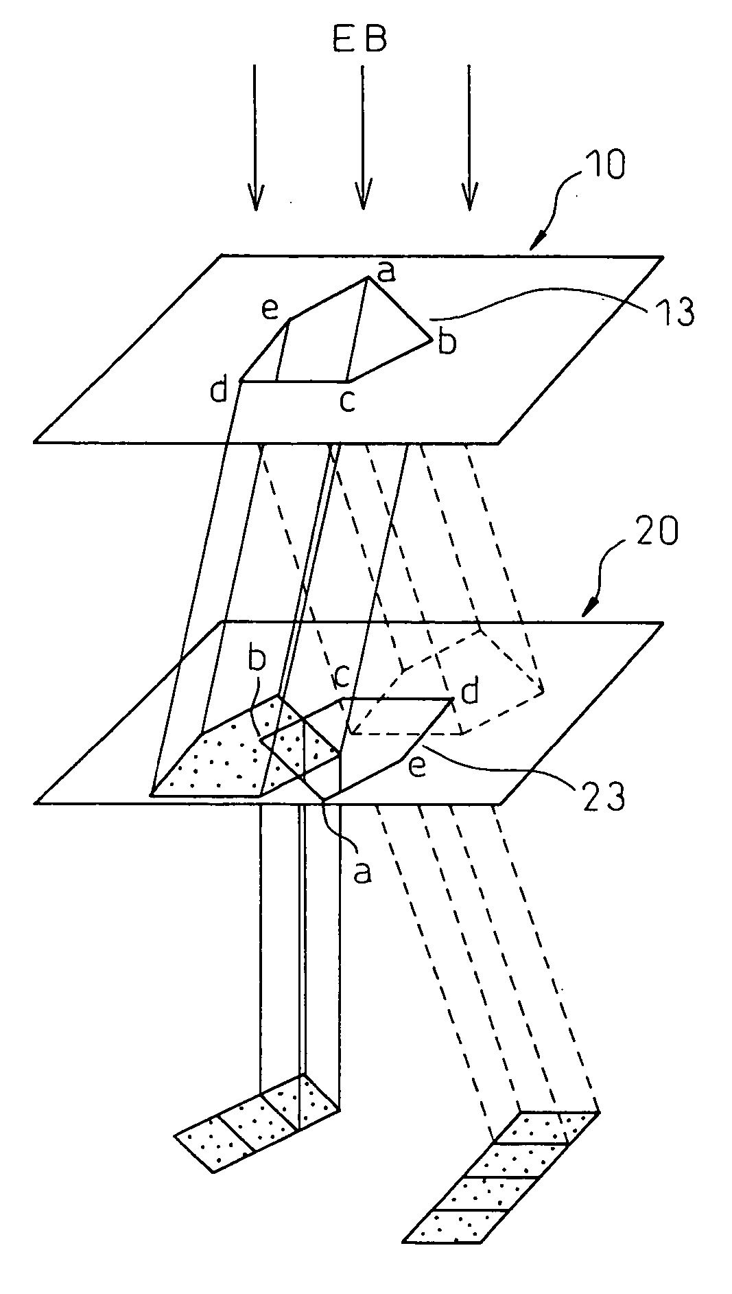
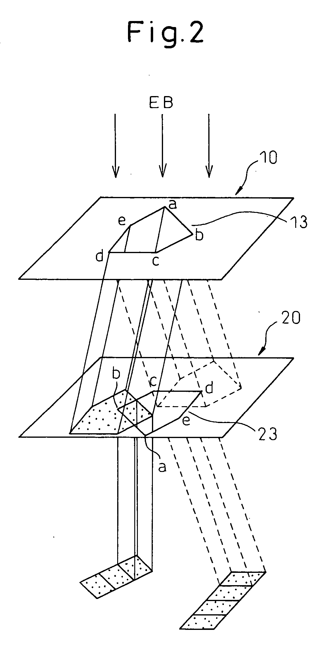
[0048]FIG. 2 is a perspective view showing the variable rectangle-type electron beam exposure apparatus of the present invention, FIGS. 3(a) and 3(b) are plan views showing shapes of the pentagonal aperture formed in the slit member, and FIG. 4 is a view showing an outline of the exposure apparatus of the this embodiment.

[0049] As shown in FIG. 3(a), one pentagonal aperture 13 is formed in the first slit member 10, the shape of which is a flat-plate-shape. This pentagon is formed in such a manner that the two angles “a” and “b” adjoining each other and the angle “d” not adjoining these two angles are respectively formed into 90°, and the residual two angles “c” and “e” are respectively formed into 135°, that is, this pentagon is formed into a “base” shape, such as that used in baseball game.

[0050] As shown in FIG. 3(b), one pentagonal aperture 23 is formed in the second slit member (pattern block mask) 20, the shape of which is a flat-plate-shape, which is arranged in parallel with...


PUM


Abstract

A variable rectangle-type electron beam exposure apparatus for forming rectangular beams of different angles which is capable of highly finely conducting exposure with respect to a predetermined fine line pattern having an arbitrary angle in the pattern region. The apparatus includes a first slit member (10) in which a plurality of rectangular apertures (11, 12) are respectively arranged by different angles; a second slit member (20) in which a plurality of rectangular apertures (21, 22) which are respectively positioned in parallel with the corresponding rectangular apertures of the first slit member, are arranged; and a deflecting unit (40) for deflecting an electron beam, which has been transmitted through a plurality of apertures of the first slit member, so that, when the electron beam transmitted through the first aperture of the first slit member is transmitted through the corresponding first aperture of the second slit member, the electron beam transmitted through the apertures except for the first aperture of the first slit can be intercepted by the second slit member.

Description

CROSS REFERENCE TO RELATED APPLICATION [0001] This application is a continuation-in-part application of Ser. No. 11 / 055,107 filed on Feb. 11, 2005.TECHNICAL FIELD [0002] The present invention relates to a pattern exposure technique for forming a circumferential or radial pattern on a disk-shaped recording medium of a magnetic disk device by utilizing a pattern forming technique which is used in the field of manufacturing a wiring board or semiconductor package. More particularly, the present invention relates to a variable rectangle-type electron beam exposure apparatus in which exposure is conducted with a rectangular beam. The present invention also relates to a pattern forming method for exposing and forming a pattern with the variable rectangle-type electron beam exposure apparatus described above. BACKGROUND ART [0003] In order to provide magnetic disk devices having a large memory capacity, the recording density of a disk-shaped recording medium has been increased every year. ...

Claims


Application Information

Patent Timeline
Patent Type & Authority Applications(United States)
IPC IPC(8): G21K5/10
CPCB82Y10/00B82Y40/00G21K1/08H01J37/3174H01J2237/31776
Inventor MIYAJIMA, MASAAKINAKAMURA, YUTAKAHOSHINO, HIROMI
Owner FUJITSU MICROELECTRONICS LTD
Learn More