
Motor-driven brake system

a technology of motor-driven brakes and brake pads, which is applied in the direction of brake systems, braking components, transportation and packaging, etc., can solve the problems of high power consumption, unsatisfactory motor-driven brake systems, and long time-consuming power consumption, so as to avoid excessive power consumption and reduce power consumption.

Active Publication Date: 2006-08-03
HITACHI ASTEMO LTD
View PDF6 Cites 33 Cited by
  • Summary
  • Abstract
  • Description
  • Claims
  • Application Information

AI Technical Summary

Benefits of technology

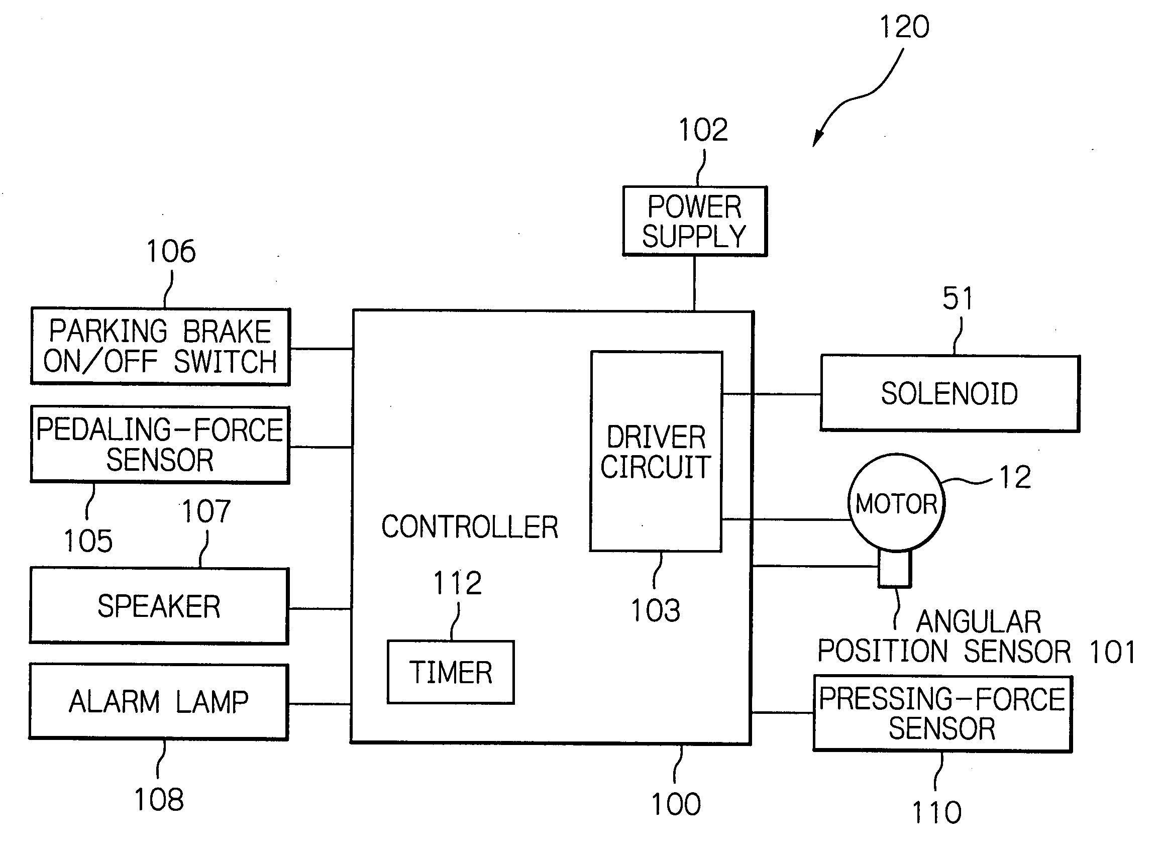
The present invention is a motor-driven brake system that aims to avoid excessive power consumption. It predicts when the brakes will start to cool down and reduces power supply to each member, stopping the brakes from consuming excessive power. This results in a more efficient and effective braking system.

Problems solved by technology

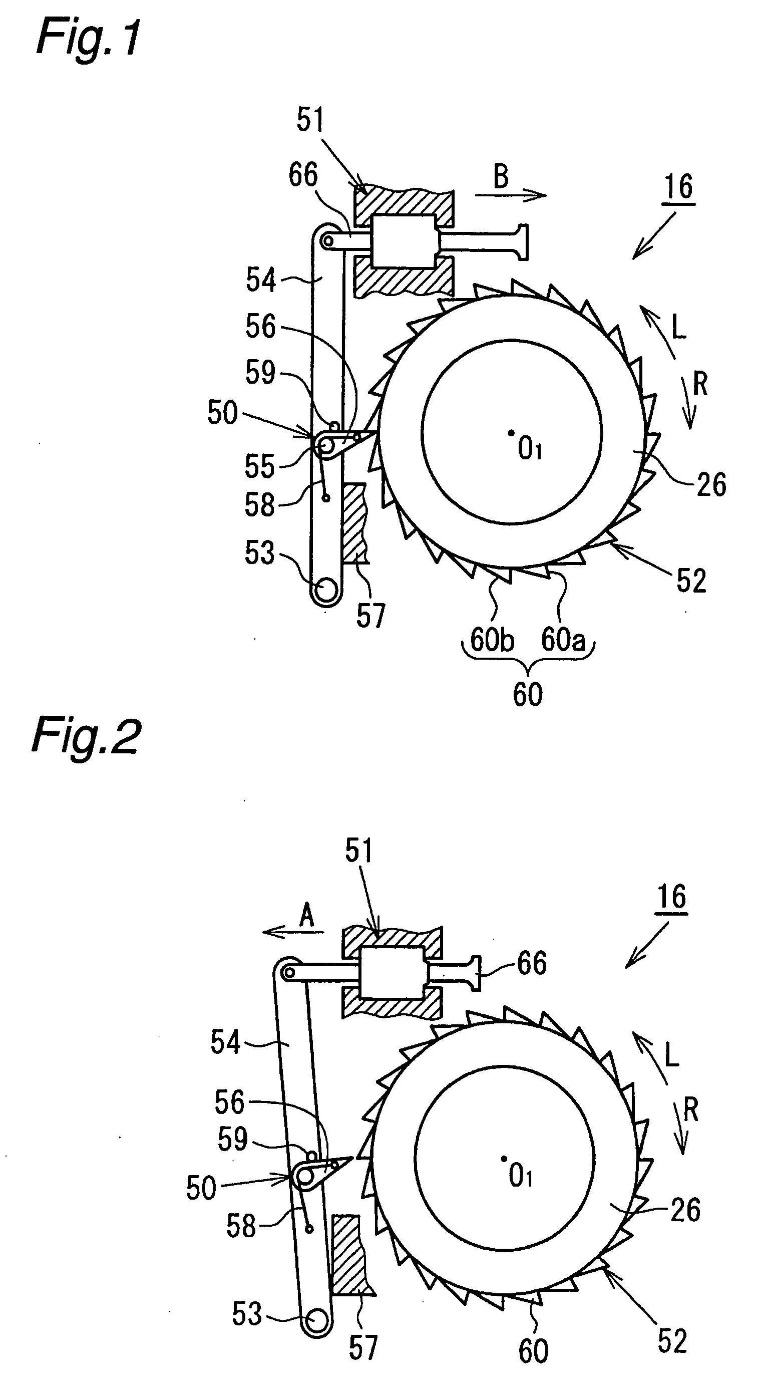
Due to this engagement between the engaging pawl and the ratchet wheel, rotation of the rotor in the direction for releasing the brake is restricted, thus exerting a parking brake function.
In this case, when the parking brake is actuated many times, the power supply of the motor-driven brake system cannot be turned off for a long time period, which leads to a high consumption of power.
Therefore, this motor-driven brake system is still unsatisfactory.
Therefore, power is consumed over a long time period.
Therefore, as in the case of the former system, this motor-driven brake system is also still unsatisfactory.

Method used


Image

  • Motor-driven brake system
  • Motor-driven brake system
  • Motor-driven brake system

Examples


Embodiment Construction

[0030] Hereinbelow, an embodiment of the present invention will be described in detail, referring to the accompanying drawings.

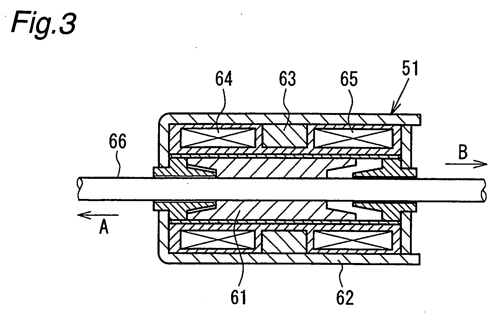
[0031]FIGS. 4 and 5 show an entire construction of a motor-driven brake system according to an embodiment of the present invention. In these drawings, reference 1 denotes a carrier fixed to a non-rotatable portion (such as a knuckle) of a vehicle body located on an inner side of the vehicle body relative to a disk rotor D. Reference numeral 2 denotes a caliper supported by the carrier 1 so as to be capable of performing a floating motion in an axial direction of the disk rotor D. Reference numerals 3 and 4 denote a pair of brake pads disposed on opposite sides of the disk rotor D. The brake pads 3 and 4 are supported by the carrier 1 so as to be capable of moving in the axial direction of the disk rotor D. The caliper 2 comprises a caliper body 10 in the form of an assembly. The caliper body 10 comprises a claw member 5 including a claw portion 5a, an annul...


PUM


Abstract

The present invention provides a motor-driven brake system comprising: a brake body for enabling brake pads to be pressed against a disk rotor attached to a member which supports a wheel of a vehicle, to thereby brake the wheel under a pressing force, the brake pads being adapted to be driven by means of an electric device; a pressing-force maintaining mechanism for maintaining the pressing force generated by the brake body, to thereby effect a parking brake operation; pressing-force detecting means adapted to detect the pressing force generated by the brake body; and a control device for controlling the electric device and the pressing-force maintaining mechanism, the control device comprising: elapsed time measuring means adapted to measure elapsed time during the parking brake operation by the pressing-force maintaining mechanism; and pressing-force reduction predicting means adapted to predict, based on the elapsed time measured by the elapsed time measuring means and a value of the pressing force as detected by the pressing-force detecting means when the elapsed time is measured, a magnitude of the pressing force generated by the brake body after the elapsed time.

Description

BACKGROUND OF THE INVENTION [0001] The present invention relates to a motor-driven brake system for generating a braking force by means of a torque of a motor. More specifically, the present invention relates to a motor-driven brake system provided with a parking brake function. [0002] A motor-driven brake system of this type comprises a brake body including a caliper having provided therein a piston, a motor and a rotary-linear motion conversion mechanism for enabling rotation of the motor to be converted to a linear motion and transmitted to the piston. Thrust is imparted to the piston according to a rotation of a rotor of the motor, to thereby press a brake pad against a disk rotor, thus braking a wheel under a pressing force (generated braking force). Normally, in such a motor-driven brake system, a force applied by a driver to a brake pedal, or a stroke of the brake pedal, is detected by a sensor, and rotation (an angle of rotation) of the motor is controlled based on a value d...

Claims


Application Information

Patent Timeline
Patent Type & Authority Applications(United States)
IPC IPC(8): B60T13/66
CPCB60T13/746F16D65/18F16D2066/005F16D2121/24F16D2125/36F16D2125/40F16D2127/06
Inventor YAMAGUCHI, TOHMAOHTANI, YUKIO
Owner HITACHI ASTEMO LTD
Learn More