Single-ended Arc Discharge Vessel with a Divider Wall

a single-ended, arc discharge technology, applied in the direction of discharge tube/lamp details, discharge tube luminescnet screens, gas-filled discharge tubes, etc., can solve the problems of linear ceramic discharge vessels that do not fully utilize the high temperature resistance of ceramics, designers of such vessels have had difficulty in finding ways to operate arc discharge vessels at a high temperature, etc., to achieve the effect of prolonging the arc gap length

Inactive Publication Date: 2006-08-03
OSRAM SYLVANIA INC
View PDF18 Cites 8 Cited by
  • Summary
  • Abstract
  • Description
  • Claims
  • Application Information

AI Technical Summary

Benefits of technology

[0006] A further object of the present invention is to provide a novel single-ended arc discharge vessel that provides a longer arc gap length for a given overall vessel length.
[0007] A yet further object of the present invention is to provide a novel single-ended arc discharge vessel that has a U-shaped arc discharge chamber and two electrodes that are next to each other at the same end of the vessel, where the two electrodes have end portions that are each in a different distal end of the U-shaped arc discharge chamber, thereby moving the vessel cold spot, and consequently the molten salt condensate, away from the electrodes.

Problems solved by technology

Prior art arc discharge vessels have temperature and size characteristics that have presented problems for designers of such vessels.
However, linear ceramic discharge vessels do not fully utilize the high temperature resistance of ceramics.
This is problematic because the electrode feedthroughs are usually sealed to the ceramic vessel with a frit material, e.g., a Dy2O3—Al2O3—SiO2 glass-ceramic, that has a lower melting point than the ceramic.
The designers of such vessels have had difficulty finding ways to operate an arc discharge vessel at a high temperature while accommodating the temperature limitations of the frit material.
However, a longer arc gap increases the overall length of the vessel.
Lamp size constraints can limit the size of the vessel and therefore limit the lamp operating voltage.
Further, in mercury-reduced or mercury-free lamps, the loss of mercury decreases lamp voltage which can make them incompatible with existing ballasts that are designed to operate at a higher lamp voltage.

Method used


Image

  • Single-ended Arc Discharge Vessel with a Divider Wall
  • Single-ended Arc Discharge Vessel with a Divider Wall
  • Single-ended Arc Discharge Vessel with a Divider Wall

Examples


embodiment 40

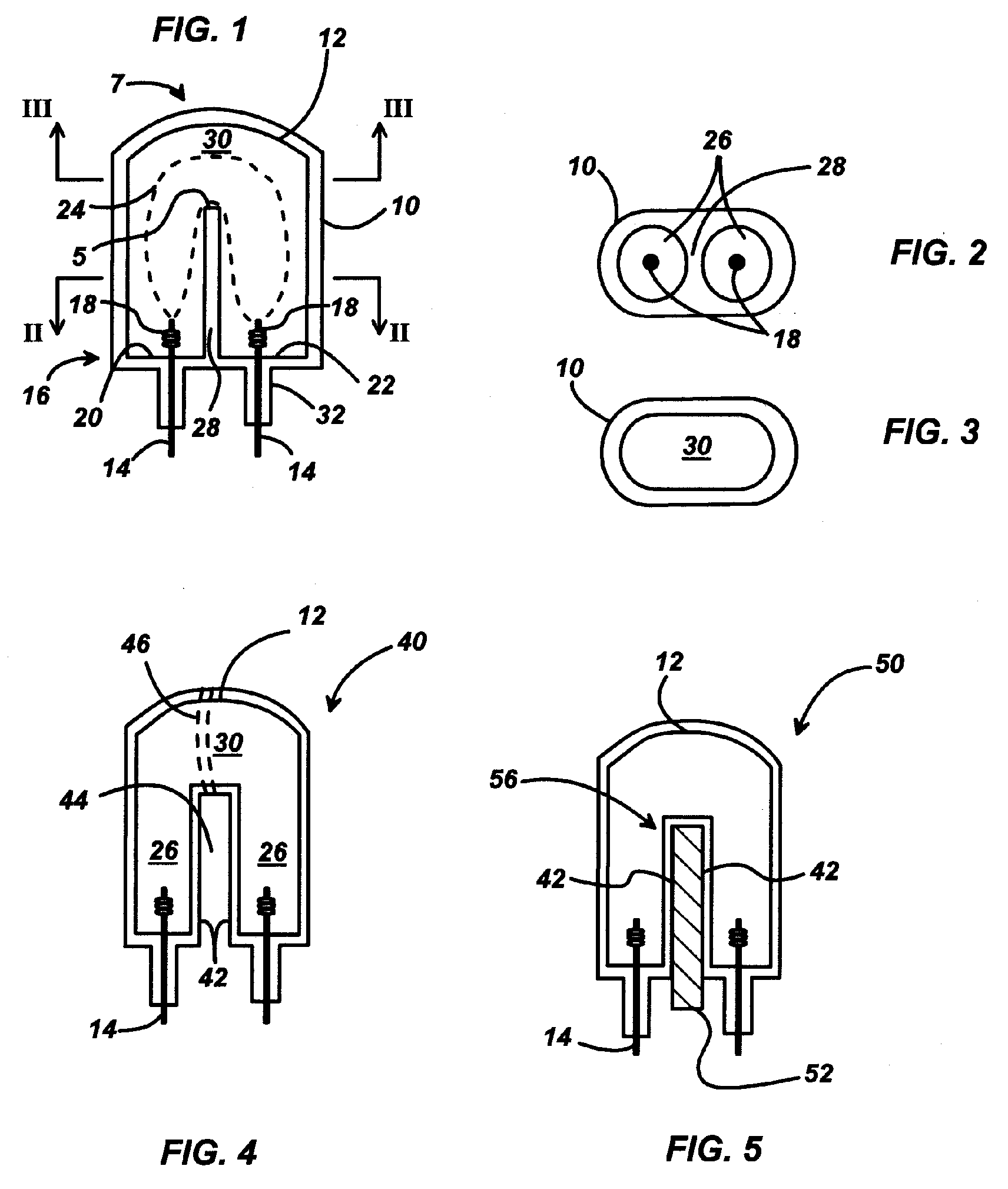
[0027] In a further embodiment 40 shown in FIG. 4, the dividing wall is formed by the interior walls 42 of the two subchambers 26 that have a gap 44 between them. The gap may be open to the ambient environment and may have a size appropriate for the type of lamp. A gap width of approximately 5 mm has been found to be suitable in a test lamp. In this embodiment, a heat sink to carry heat away from the hot spot at the top end of the dividing wall may be provided by wrapping a heat conducting wire 46 around the passageway 30 at the upper end of the gap 44.

embodiment 50

[0028] In yet a further embodiment 50 shown in FIG. 5, the dividing wall includes a heat conductive member 52, such as heat conductive metal, that carries heat away from the interior walls 42 of the arched interior portion 56 of the arc discharge chamber 12 to an external heat sink (not shown).

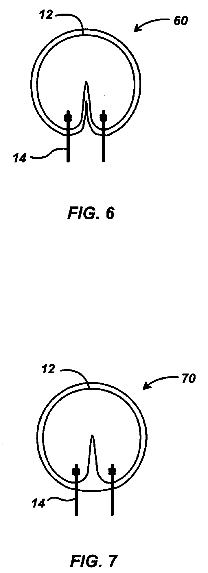
[0029] Two additional embodiments are shown in FIGS. 6-7. The vessels 60, 70 have rounded shapes to help control vessel temperature.

[0030] In any of the embodiments, it is possible to control and decrease the dividing wall temperature by making the dividing wall thicker.


PUM


Abstract

A single-ended arc discharge vessel for a metal halide lamp includes a U-shaped arc discharge chamber that has two juxtaposed subchambers with a divider wall therebetween and a passageway around the divider wall that connects the two subchambers to each other. The vessel has two parallel electrodes in a same end of the vessel that is opposite the passageway. Each of the electrodes extends into a respective one of the two subchambers a distance less than a height of the divider wall so that the arc discharge between the electrodes is U-shaped. This arrangement moves the vessel cold spot away from the electrodes to permit higher operating temperatures and increases arc gap length for a given vessel size to permit a higher lamp voltage.

Description

BACKGROUND OF THE INVENTION [0001] The present invention is directed to an arc discharge vessel for a metal halide lamp. [0002] Prior art arc discharge vessels have temperature and size characteristics that have presented problems for designers of such vessels. In a typical linear configuration, electrodes are positioned on a central axis at opposite ends of the discharge vessel for striking an arc therebetween. The discharge vessel is hermetically sealed and contains a chemical fill that may comprise mercury and a mixture of metal halide salts, e.g., Nal, Cal2, DyI3, HoI3, TmI3, and TlI. The discharge chamber will also contain a buffer gas, e.g., 30 to 300 torr Xe or Ar. The arc discharge vessel is desirably operated at a relatively high temperature to vaporize the metal halide salts. In vertically operated lamps, the molten salt condensate in these vessels collects near the base of one or both of the electrodes since this is where the temperatures tend to be lowest, i.e., the cold...

Claims


Application Information

Patent Timeline
Patent Type & Authority Applications(United States)
IPC IPC(8): H01J17/16H01J61/30
CPCH01J61/103H01J61/325H01J61/33H01J61/52H01J61/827
Inventor BROCK, LORI R.DREEBEN, THOMAS D.
Owner OSRAM SYLVANIA INC
Why Eureka
Try Eureka