Direct heating tube and method of heating fluid using same

a technology of direct heating and heating fluid, which is applied in the direction of ohmic-resistance heating, water heaters, water circulation, etc., can solve the problems of risk, heat tubes, and conventional methods of heating columns, and achieve uniform temperature distribution, sufficient cooling rate, and sufficient heating rate

Active Publication Date: 2007-05-17
GL SCI
View PDF5 Cites 9 Cited by
  • Summary
  • Abstract
  • Description
  • Claims
  • Application Information

AI Technical Summary

Benefits of technology

[0020] According to the present invention described above, the direct heating tube has a sufficient heating rate and a sufficient cooling rate, and has no cold spots therein, with the result that it has become possible to ensure a uniform temperature distribution in the whole part thereof and a temperature distribution having a desired temperature gradient, and that it has become possible to keep constant the temperature of a fluid which is caused to flow through the tube or to give a desired change to the temperature of the fluid. When heated, the direct heating tube does not exert an adverse influence any more on devices near the tube, such as a detector and an oven, even by heating the tube. Furthermore, the direct heating tube could be given a simple construction which is capable of being manufactured at low cost. And designs in which the ease of assembling is considered became possible for an electrode portion of the direct heating tube.

Problems solved by technology

However, these conventional methods of heating a column, a heat tube and the like have had the following problems.
Although the first method can be very easily carried out, for example, when as in the case of a cryotrap used in a gas chromatograph, cooling and heating are alternately performed and the temperature change of the cryotrap is severe, the electrical insulation of a heater may sometimes be broken, thus involving risk.
Therefore, it is necessary to select and use a heater having a sufficient insulation distance and safe watt density in terms of design, with the result that the rate at which the tube is heated may not be sufficient.
That is, the higher the temperature rise rate, the narrower the sample band, thereby making it possible to detect the sample with high sensitivity, and the lower the temperature rise rate, the wider the sample band, thereby making it impossible to detect the sample with high sensitivity.
Also the second method has the greatest weak point that the heating rate is low in the same manner as the first method.
That is, because the specific heat capacity of gases is very small, it is necessary to cause a large volume of a high-temperature gas to flow at a time if rapid heating is required.
However, in order to realize this, large-scale equipment becomes necessary and the manufacturing cost also rises.
However, in the conventional direct heating method, heat mass is present in electrode portions at both ends and, therefore, this poses the problem that there are low-temperature areas, which are what is called cold spots, in both end portions.
However, much time is required before the sample introduction portion is heated because of a large thermal capacity and inversely when cooling is performed, much time is required.
Thus, the fourth method has exerted an undesirable influence on a detector, an oven and the like.

Method used


Image

  • Direct heating tube and method of heating fluid using same
  • Direct heating tube and method of heating fluid using same
  • Direct heating tube and method of heating fluid using same

Examples


embodiment 1

[0051]FIG. 5 is a longitudinal sectional view of an embodiment in which a direct heating tube 1 of the present invention is used in a sample introduction portion of a gas chromatogram. A first heated tube 2 constitutes a sample vaporization portion, a flange 4 is implanted in a standing manner radially from a lower end of the first heated tube 2, and a second heated tube 3 is installed at a peripheral end of the annular flange 4 made of a sheet to the roughly middle point of the first heated tube 2 concentrically with the first heated tube 2. As with the sample introduction portion of a usual gas chromatogram, this sample introduction portion is constituted by a column 80, a liner 81, a carrier gas line 82, a discharge line 83, a septum 84 and the like. The first heated tube 2 and the second heated tube 3 and the flange 4 are assembled by welding. A flange 71 is provided in an upper end portion of the second heated tube 3, a tube 72 is provided at a peripheral end of the flange 71, ...

embodiment 2

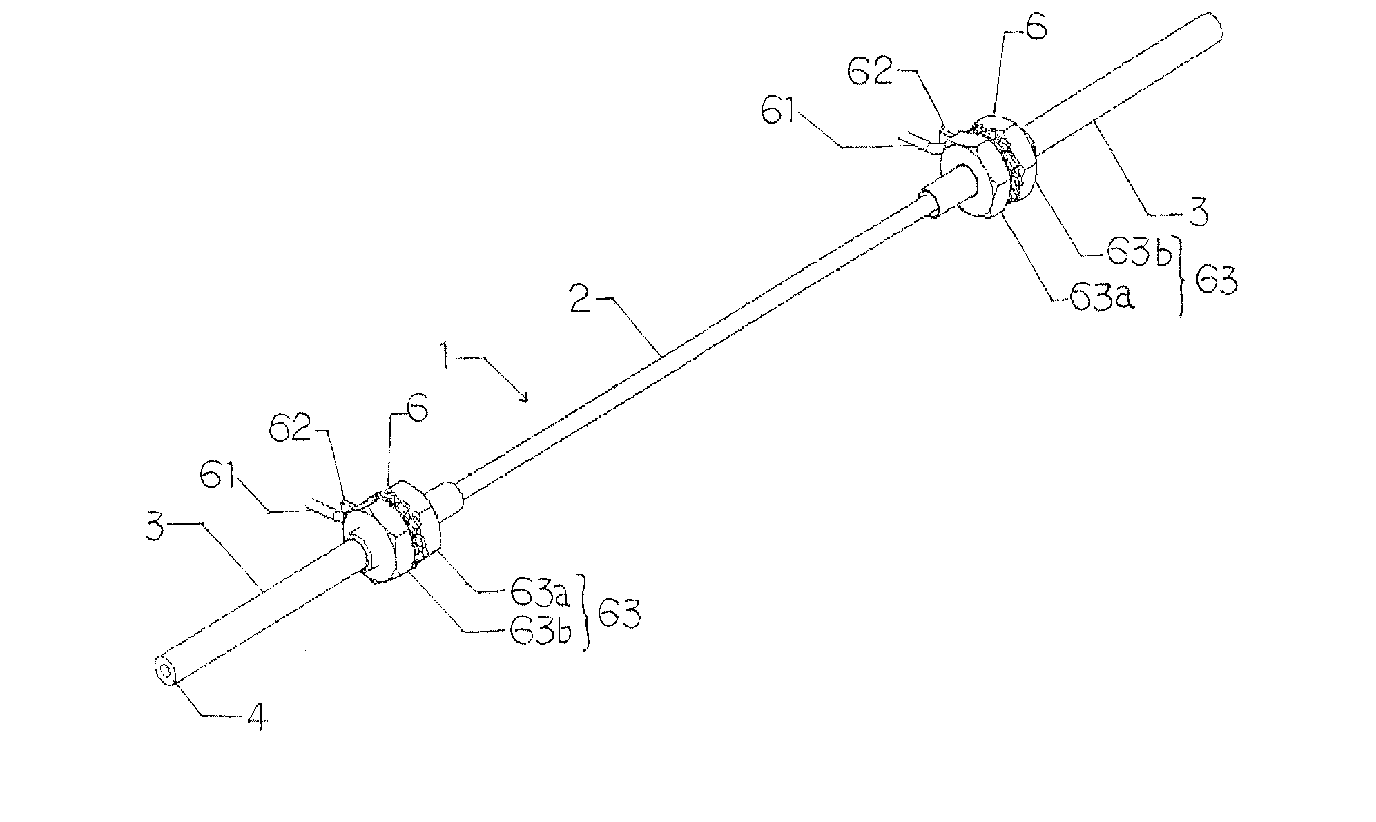
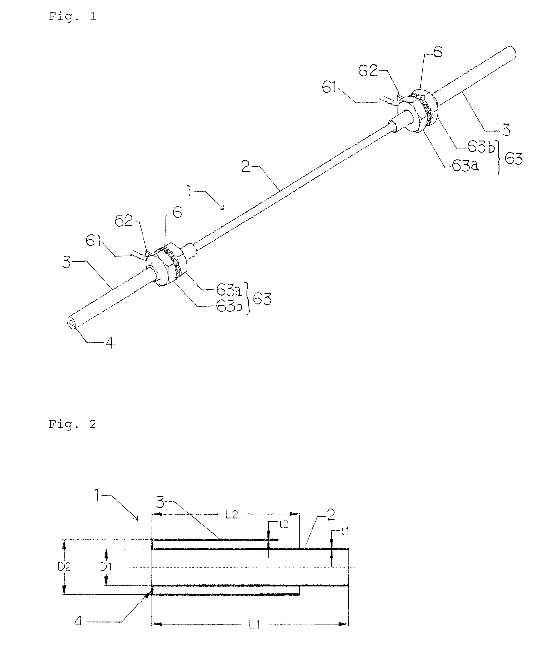
[0053]FIG. 8 is a longitudinal sectional view of an embodiment in which a direct heating tube of the present invention is applied to a column for a cryotrap of a gas chromatogram. In the tube 1, the first heated tube 2 had a total length of 100 mm, the first heated tube 2 had an inner diameter of 1 mm and a wall thickness of 0.05 mm, annular sheet flanges 4, 4 having a height of 0.95 mm from both end portions of the first heated tube 2 were formed, second heated tubes 3 were installed from the flange 4 concentrically with the first heated tube 2, and the second heated tubes 3 each had a length of 30 mm, an inside diameter of 3 mm, and a wall thickness of 0.05 mm. For an electrode portion 6, a conductor 61 was connected to an electrode plate 62, the second heated tube 3 was inserted through the electrode plate 62 and fixed by being supported from both sides thereof by use of a double nut 63. Thus, the electrode portion 6 was installed in a position 20 mm from the flange 4. The materi...

embodiment 3

[0054]FIG. 9 is a longitudinal sectional view of an embodiment in which a direct heating tube of the present invention is applied to a connection between a column end of a gas chromatogram and a detector 5 (here, an FID) A heat tube having a total length of 60 mm was used as a tube 1. Flanges 4, 4 were provided at both ends of a first heated tube 2 having a total length of 60 mm and an outside diameter of 1.6 mm, and second heated tubes 3, 3 having a total length of 24 mm were provided from peripheral end portions of the flanges 4, 4 toward the center of the first heated tube 2. The material for the first heated tube 2 and the second heated tube 3 is stainless steel. An annular sheet flange 4 having a width of 0.8 mm is used as the flange 4 on the detector 5 side of the heat tube. However, in the connection between the first heated tube 2 and the second heated tube 3 on the column side, a column connection port 49 made of stainless steel is used as the flange 4. As the fabrication m...


PUM


Abstract

Provided is a direct heating tube which has a sufficient heating rate and a sufficient cooling rate, and has no cold spots therein, making it possible to ensure a uniform temperature distribution in the whole part thereof or a temperature distribution having a desired temperature gradient, and making it possible to keep constant the temperature of a fluid which is caused to flow through the tube or to give a desired change to the temperature of the fluid. Provided also is a direct heating tube which does not exert an adverse influence on devices near the tube, such as a detector and an oven, even by heating the tube. In a desired portion of the tube to be heated, a second heated tube connected to a first heated tube is provided outside the first heated tube, and an electrode portion is connected to the second heated tube.

Description

TECHNICAL FIELD [0001] The present invention relates to a direct heating tube which heats a fluid by heating the tube during the passage of fluids such as liquids and gases. More particularly, it relates to a direct heating tube which is directly heated by connecting an electrode to the tube and causing a DC current or an AC current to flow directly in the tube, such as a column which is heated in a gas chromatograph, a heat tube (a transfer line) for keeping warm a column to introduce samples from an analysis column to an ionization chamber in a heated tube at a sample injection port of a gas chromatograph or a gas chromatograph-mass spectrometer (GC / MS), and a heated tube which is used to introduce samples from the column of a gas chromatograph into a detector, such as a hydrogen flame ionization detector (FID). BACKGROUND ART [0002] In a gas chromatograph, before the introduction of a sample into a separation column which performs the separation of components, it is general pract...

Claims


Application Information

Patent Timeline
Patent Type & Authority Applications(United States)
IPC IPC(8): F22D7/00F24H1/10H05B3/42
CPCF24H1/142H05B3/42
Inventor KURANO, MITSUHIRO
Owner GL SCI
Why Eureka
Try Eureka