Internal multiband antenna

a multi-band antenna and antenna technology, applied in the direction of antennas, antenna details, antenna earthings, etc., can solve the problems of difficult to make the upper operating band of the antenna sufficiently wide, parasitic elements are relatively sensitive to external conductive materials, and the adaptability of the antenna can become a problem, so as to increase the effect of the electric length of the elements and improve the matching of the antenna

Inactive Publication Date: 2006-08-03
PULSE FINLAND
View PDF7 Cites 22 Cited by
  • Summary
  • Abstract
  • Description
  • Claims
  • Application Information

AI Technical Summary

Benefits of technology

[0008] The invention has the advantage that external elements, especially the radio device user's hand, do not significantly impair the antenna matching on the operating band which has partially been formed with the parasitic element. This is due to the fact that the parasitic element is located in the central area of the whole radiator plane, and not in its peripheral area. For the same reason the battery of the radio device does not significantly impair the efficiency of the antenna on the band of the parasitic element, which impairment is common in prior art devices. In addition, the invention further has the advantage that when the resonance frequency based on the parasitic element is on the upper operating band, the antenna matching is also improved on the lower operating band compared to the prior art. Furthermore, the invention has the advantage that an antenna operating on certain frequencies can be made smaller than a corresponding prior art antenna. This is due to the fact that the coupling between the parasitic element and the conductor branch corresponding to the lower operating band of the PIFA has a strongly increasing effect on the electric lengths of the elements.

Problems solved by technology

However, in that case the adaptation of the antenna can become a problem.
It is especially difficult to make the upper operating band of the antenna sufficiently wide when it is wanted to cover the bands used by two systems.
The structure according to FIG. 1 has the drawback that the parasitic element is relatively sensitive to external conductive materials.
Therefore, the mobile phone user's hand can significantly impair the band properties of the antenna.

Method used


Image

  • Internal multiband antenna
  • Internal multiband antenna
  • Internal multiband antenna

Examples


Embodiment Construction

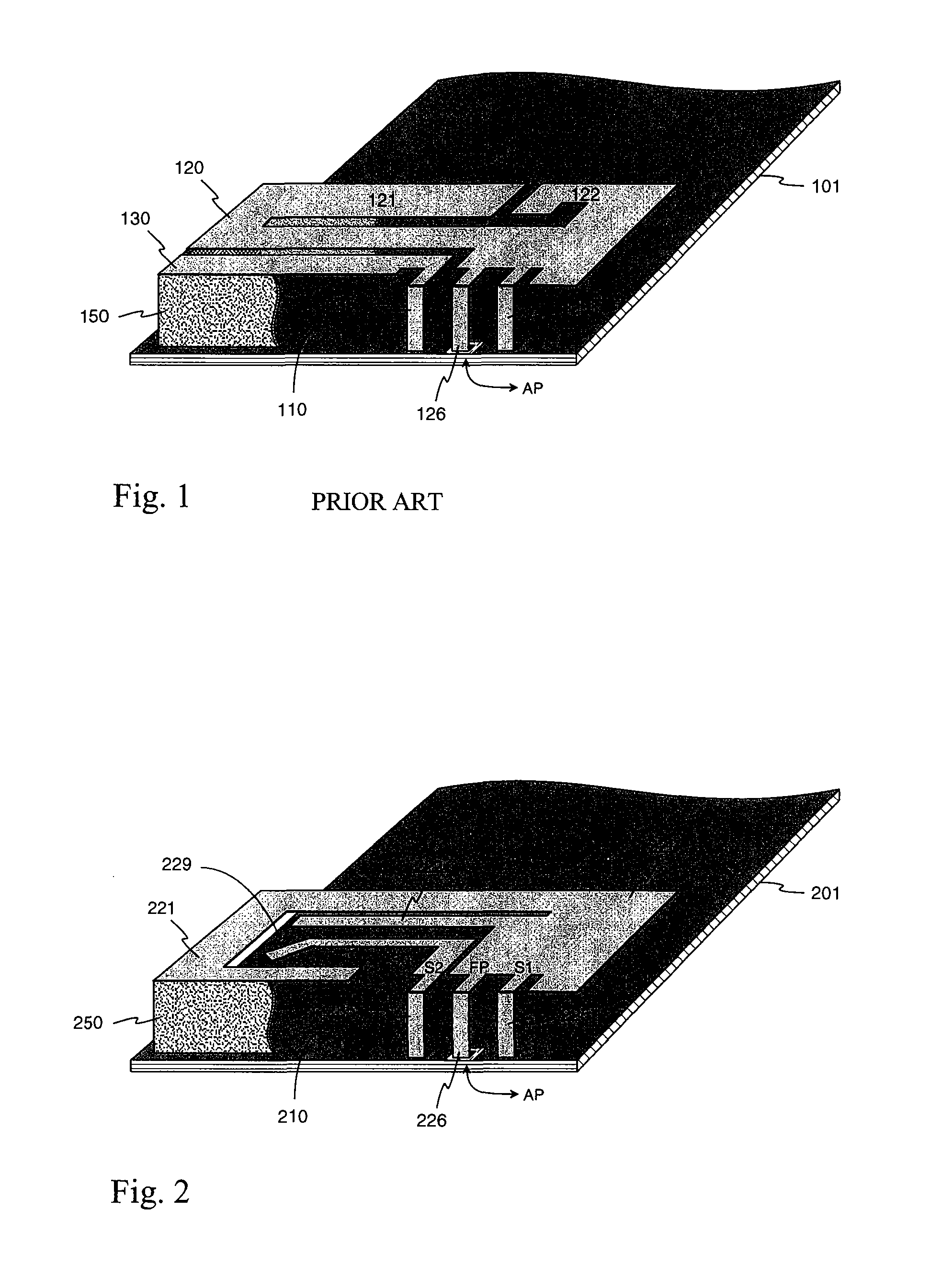
[0016]FIG. 1 was dealt with above in connection with the description of the prior art.

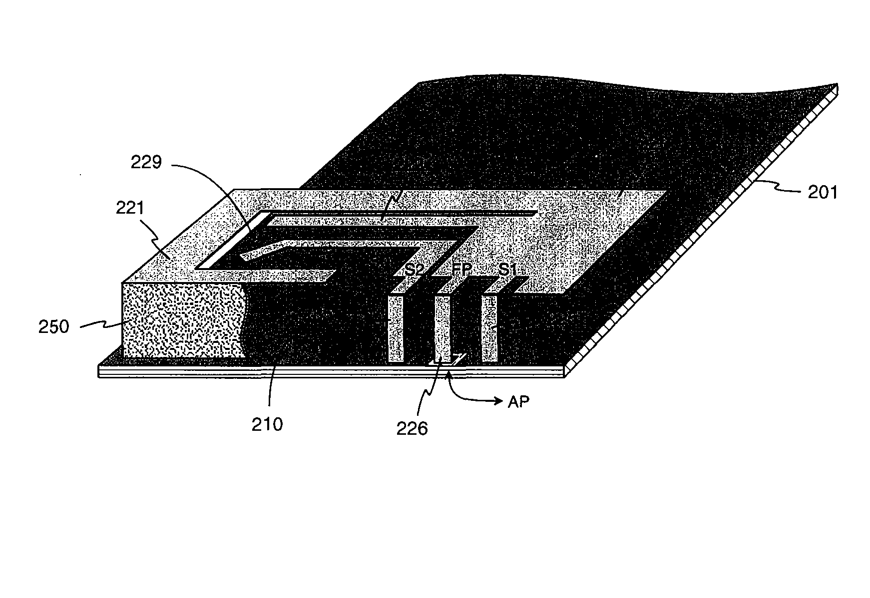
[0017]FIG. 2 shows an example of an internal multiband antenna according to the invention. In the figure there is a circuit board 201 of a radio device with a conductive upper surface, which operates as the ground plane 210 of the antenna. At the one end of the circuit board, above the ground plane, there is the radiating plane 220 of the antenna, which has a rectangular outline. The first short-circuit conductor 225, connecting the radiating plane to the ground plane, starts from the edge of the radiating plane, one of its long sides. Its connecting point in the radiating plane is called the first short-circuit point S1. Close to the first short-circuit point in the radiating plane, there is the feed point FP of the whole antenna, from which the feed conductor 226 of the antenna starts. From the feed conductor there is a ground-isolated lead-through to the antenna port AP on the lower surface of ...


PUM


Abstract

The invention relates to an internal multiband antenna intended for small-sized radio devices, and a radio device with such an antenna. The basic structure of the antenna is a two-band PIFA. A parasitic element (230) is added to it inside the outline of the radiating plane (220) of the PIFA, e.g. in the space (229) between the conductor branches (221, 222) of the radiating plane. The parasitic element extends close to the feeding point (FP) of the antenna, from which place it is connected to the ground plane of the antenna with its own short-circuit conductor (235). The structure is dimensioned so that the resonance frequency based on the parasitic element comes close to the one resonance frequency of the PIFA, thus widening the corresponding operating band, or a separate third operating band is formed for the antenna with the parasitic element. Because the parasitic element is located in the central area of the radiating plane and not in its peripheral area, the radio device user's hand does not significantly impair the matching of the antenna on an operating band which has been formed by the parasitic element. In addition, when the resonance frequency based on the parasitic element is on the upper operating band, the matching of the antenna also improves on the lower operating band.

Description

[0001] The invention relates to an internal multiband antenna intended for small-sized radio devices. The invention also relates to a radio device with an antenna according to the invention. BACKGROUND OF THE INVENTION [0002] Models that operate in two or more systems using different frequency ranges, such as different GSM systems (Global System for Mobile telecommunications) have become increasingly common in mobile stations. The basic condition for the operation of the mobile station is that the radiation and reception properties of its antenna are satisfactory on the frequency bands of all the systems in use. Without any limit on size, it is relatively easy to make a high-quality multiband antenna. However, in mobile stations, especially mobile phones, the antenna must be small when it is placed inside the covering of the device for comfort of use. This increases the requirements of antenna design. [0003] In practice, an antenna of sufficiently high quality that can be placed ins...

Claims


Application Information

Patent Timeline
Patent Type & Authority Applications(United States)
IPC IPC(8): H01Q1/24H01QH01Q5/00H01Q5/10H01Q5/371H01Q5/378H01Q9/04
CPCH01Q1/244H01Q5/378H01Q5/371H01Q9/0421
Inventor KORVA, HEIKKI
Owner PULSE FINLAND
Why Eureka
Try Eureka