Medium exhibiting negative refraction, optical element, and optical system

a technology of negative refraction and optical element, applied in the field of medium exhibiting negative refraction and an optical system, can solve problems such as limited image resolution

Inactive Publication Date: 2006-08-03
OLYMPUS CORP
View PDF3 Cites 115 Cited by
  • Summary
  • Abstract
  • Description
  • Claims
  • Application Information

AI Technical Summary

Benefits of technology

[0034] a thickness of a medium having a greater absolute value of an imaginary portion of a complex refractive index from among the two optical elements is smaller than a thickness of the other medium.

Problems solved by technology

These optical systems have had a disadvantage that image resolution is limited due to diffraction caused by undulation property of an optical or electromagnetic wave.

Method used


Image

  • Medium exhibiting negative refraction, optical element, and optical system
  • Medium exhibiting negative refraction, optical element, and optical system
  • Medium exhibiting negative refraction, optical element, and optical system

Examples


Embodiment Construction

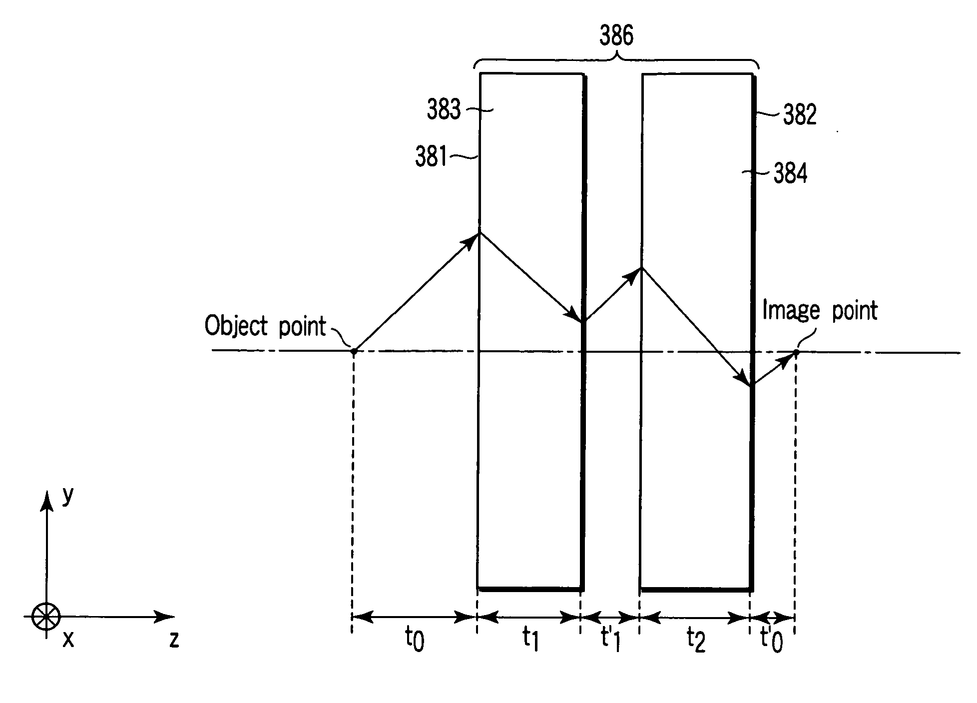
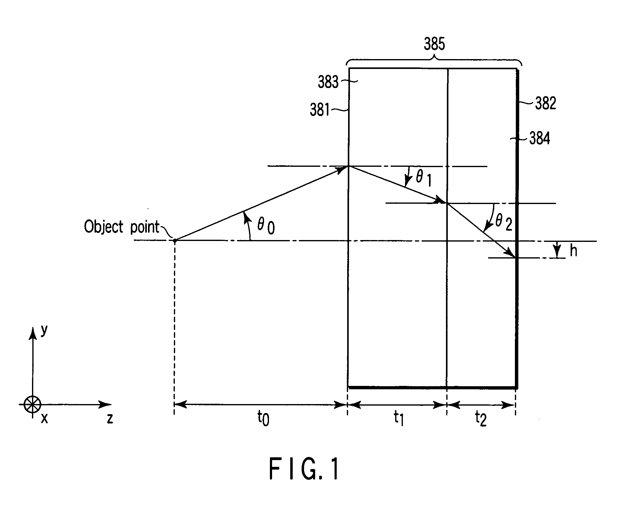
[0055] Hereinafter, embodiments of the present invention will be described in detail with reference to the accompanying drawings. FIG. 1 shows a negative refractive index medium 385 constituted by parallel flat plates 381 and 382 (hereinafter, simply referred to as flat plates) serving as optical elements formed of negative refractive index mediums 383 and 384, respectively, in one embodiment of the present invention. Here, an attempt is made to obtain an emitted light component of a light beam emitted from an object point in this system is formed as an image at a position at which complete image formation should be achieved even if an optical vibration frequency ω slightly changes.

[0056] For the sake of simplification of a description, assume that to′=0, namely, an image point exists on a right side face of the flat plate 382.

[0057] In FIG. 1, on an x-axis, a direction from a top face to a back face of paper is positive. On a y-axis, an upward direction is positive, and on a z-ax...


PUM


Abstract

An optical element using a medium exhibiting negative refraction, a carbon nano tube being used for the medium exhibiting negative refraction, is disclosed. There is also disclosed an optical system having a plurality of optical elements each formed of a medium exhibiting negative refraction, wherein the plurality of optical elements includes optical elements having different chromatic dispersions.

Description

CROSS-REFERENCE TO RELATED APPLICATIONS [0001] This application is based upon and claims the benefit of priority from prior Japanese Patent Application No. 2005-002854, filed Jan. 7, 2005, the entire contents of which are incorporated herein by reference. BACKGROUND OF THE INVENTION [0002] 1. Field of the Invention [0003] The present invention relates to a medium exhibiting negative refraction, and an optical system which includes an optical element formed of such a medium. [0004] 2. Description of the Related Art [0005] Conventionally, there has been well known: an optical element using an optical or electromagnetic wave; an optical system such as an image pickup optical system, an observation optical system, a projection optical system and a signal processing system; and an optical device using them. These optical systems have had a disadvantage that image resolution is limited due to diffraction caused by undulation property of an optical or electromagnetic wave. [0006] In order ...

Claims


Application Information

Patent Timeline
Patent Type & Authority Applications(United States)
IPC IPC(8): G02B5/18G02B27/44
CPCB82Y20/00G02B1/007G02B21/00G02B21/02G03F7/70958
Inventor NISHIOKA, KIMIHIKO
Owner OLYMPUS CORP
Why Eureka
Try Eureka