Ring-shaped light emitting unit

a light-emitting unit and ring-shaped technology, applied in the direction of instruments, measurement device, measurement apparatus components, etc., can solve the problems of unfavorable bright lines and non-uniform emission luminance, and achieve the effect of simple structure and high light utilization ra

Inactive Publication Date: 2006-08-03
TOYODA GOSEI CO LTD
View PDF1 Cites 47 Cited by
  • Summary
  • Abstract
  • Description
  • Claims
  • Application Information

AI Technical Summary

Benefits of technology

[0014] As a result of the fact that the above-described action is exhibited, the optical density of the interior of the ring-shaped light guiding member assumes a highly uniformalized state, and a high light utili

Problems solved by technology

However, in the process in which the light travels through the ring-shaped light guiding member 51, part of the light is lost, so that a portion in the vicinity of the light entering portion inevitably radiates brightly, and the light becomes the darker the further away from the vicinity of the light entering portion.
With this method, however, there is a problem in that the

Method used


Image

  • Ring-shaped light emitting unit
  • Ring-shaped light emitting unit
  • Ring-shaped light emitting unit

Examples


first embodiment

[0084] A ring-shaped light emitting unit in accordance with a first embodiment is shown FIGS. 4 to 7. FIG. 4 is a perspective view of a ring-shaped light emitting unit 1. FIG. 5 is a plan view thereof. FIG. 6 is a side elevational view of a light emitting portion (a ring-shaped light guiding member and light guiding paths) 20 of the ring-shaped light emitting unit 1. FIG. 7 is a vertical cross-sectional view of the light emitting portion 20 (a cross-sectional view taken along line VII-VII in FIG. 5). The ring-shaped light emitting unit 1 in accordance with this embodiment is used for decorating, for example, a periphery of a speaker grill. Hereafter, referring to the respective drawings, a description will be given of the structure and the form of luminescence of the ring-shaped light emitting unit 1.

[0085] The ring-shaped light emitting unit 1, if largely classified, is composed of the light emitting portion 20 and a light source 30. The light emitting portion 20 is composed of th...

second embodiment

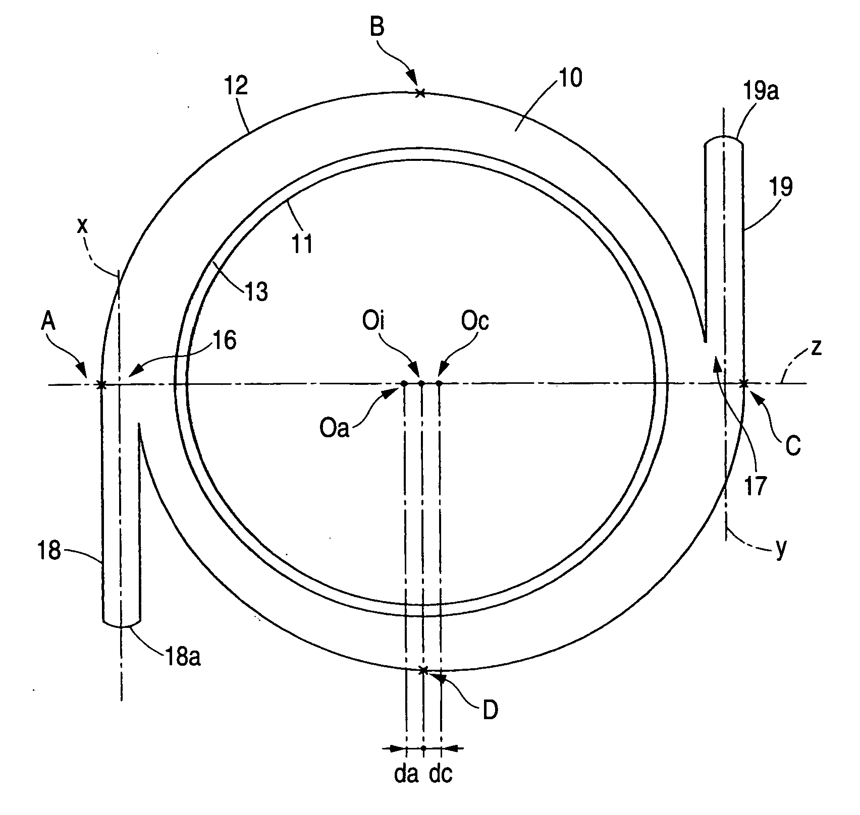
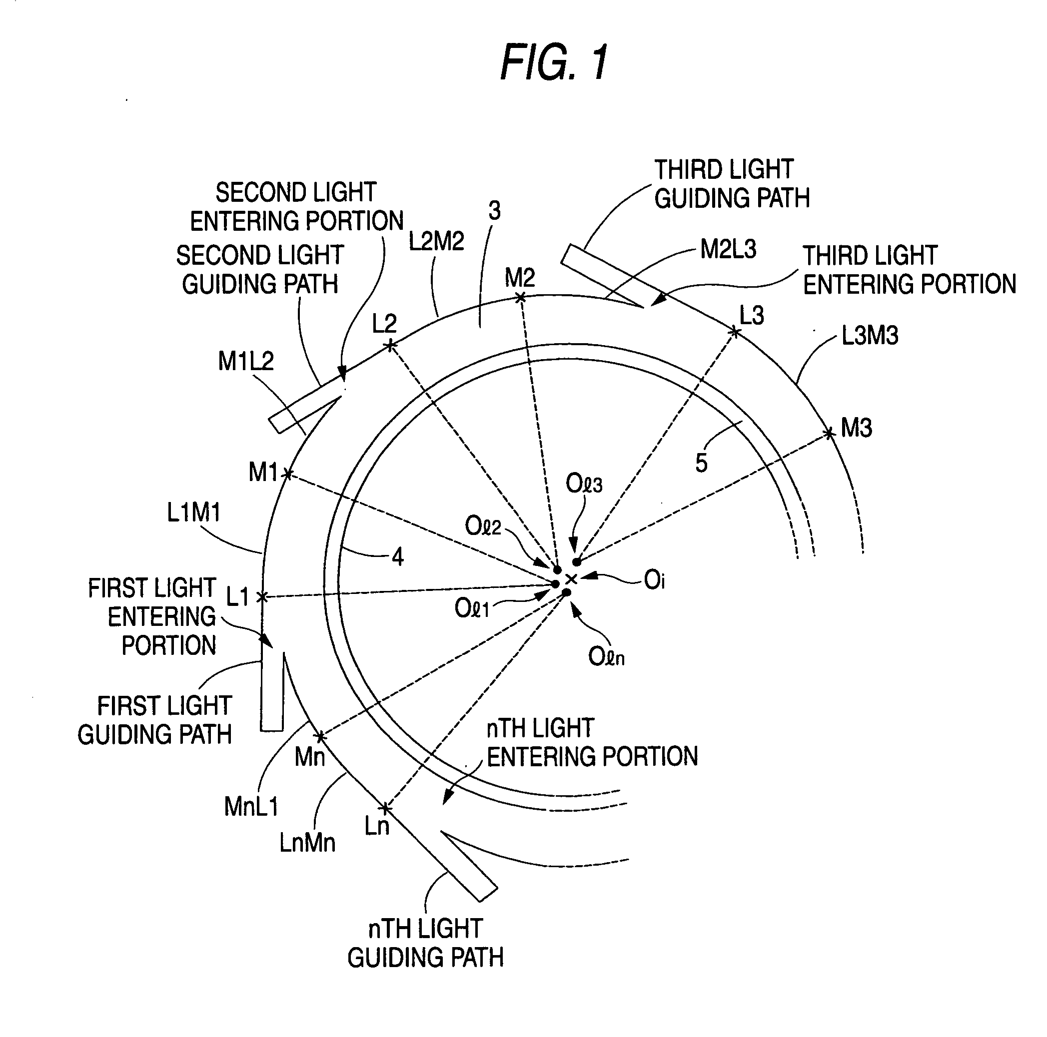
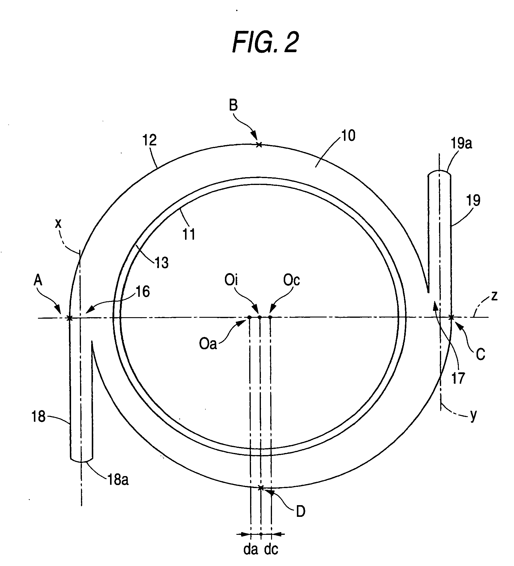
[0101]FIGS. 8 and 9 show a specific structure of a case in which the light emitting portion of the ring-shaped light emitting unit has three light guiding paths. FIG. 8 is a plan view illustrating a ring-shaped light emitting unit 2 in accordance with this embodiment. FIG. 9 is a cross-sectional view taken along line IX-IX in FIG. 8. Hereafter, referring to these drawings, a description will be given of the structure and the form of luminescence of the ring-shaped light emitting unit 2. It should be noted that matters which are not specifically referred to are assumed to be the same as those of the ring-shaped light emitting unit 1 of the above-described embodiment. In addition, those members and elements which are substantially identical to the ring-shaped light emitting unit 1 will be denoted by the same reference numerals, and a description thereof will be omitted partially.

[0102] The ring-shaped light emitting unit 2 is comprised of a light emitting portion including a ring-sha...


PUM


Abstract

A ring-shaped light emitting unit including a ring-shaped light guiding member having a light emitting surface which is continuous along an extending direction thereof, and n light guiding paths for guiding light of a light source into the ring-shaped light guiding member, the n light guiding paths being continuously connected to portions of an outer periphery of the ring-shaped light guiding member at positions rotationally symmetrical about a center of the ring-shaped light guiding member as a reference, wherein an inner periphery of the ring-shaped light guiding member is a substantially perfectly round circle in a plan view, and the outer periphery of the ring-shaped light guiding member has a shape in which circular arcs of a plurality of substantially perfectly round circles are continuously connected in a plan view, excluding light entering portions.

Description

[0001] This application is based on Japanese Patent Applications No. 2005-022278 and 2005-320237, which are incorporated herein by reference. BACKGROUND OF THE INVENTION [0002] 1. Field of the Invention [0003] The present invention relates to a ring-shaped light emitting unit. The present invention is used in the decoration of, for example, a speaker grill, a clock, or the like, or such as a speedometer or a tachometer of a vehicle (an automobile, an electric car, etc.), aircraft, or the like. [0004] 2. Description of the Related Art [0005] Against the backdrop that it has become possible to utilize compact light sources of low electric power consumption, such as LEDs, and against the backdrop of improvement in consumers' design awareness, attempts have been made to decorate various objects (e.g., vehicle upholstery products) with light. As one of such attempts, a light emitting unit has been developed in which ring-like light is obtained by using a ring-shaped light guiding member ...

Claims


Application Information

Patent Timeline
IPC IPC(8): G01D11/28
CPCG01D11/28
Inventor TAMAKI, MAKOTO
Owner TOYODA GOSEI CO LTD
Why Eureka
Try Eureka