Support system for a composite airfoil in a turbine engine

a technology of airfoil and support system, which is applied in the direction of machines/engines, stators, liquid fuel engines, etc., can solve the problems of laminates that are often damaged, laminates that are not able to absorb tensile forces, etc., and achieve the effect of increasing the ability of airfoils, reducing the likelihood of damage, and increasing the life of airfoils

Active Publication Date: 2006-08-03
SIEMENS ENERGY INC
View PDF19 Cites 38 Cited by
  • Summary
  • Abstract
  • Description
  • Claims
  • Application Information

AI Technical Summary

Benefits of technology

[0005] This invention relates to a turbine airfoil support system for supporting composite turbine airfoils in a turbine assembly. In at least one embodiment, the turbine airfoil support system may attach a turbine airfoil with platforms to shrouds such that compression forces are transmitted from the shrouds to the perimeter of the airfoil. Application of the compressive load to the airfoil at the perimeter of the airfoil increases the ability of the airfoil to accommodate tensile forces and thus, increases the life of an airfoil. By placing the perimeter of an airfoil in compression, the composite airfoil is less likely to be damaged from thermal stresses encountered during normal turbine engine operation. In particular, the compression forces applied at the perimeter of the airfoil reduce the thermal stresses on the fillets at the intersection between the airfoil and attached platforms.

Problems solved by technology

In addition, turbine airfoils often contain internal cooling systems for prolonging the life of the airfoils and reducing the likelihood of failure as a result of excessive temperatures.
Thus, laminates are often not capable of absorbing tensile forces that are encountered in a turbine engine environment.
Rather, laminates often are damaged by tensile forces during normal engine operation.

Method used


Image

  • Support system for a composite airfoil in a turbine engine
  • Support system for a composite airfoil in a turbine engine
  • Support system for a composite airfoil in a turbine engine

Examples


Embodiment Construction

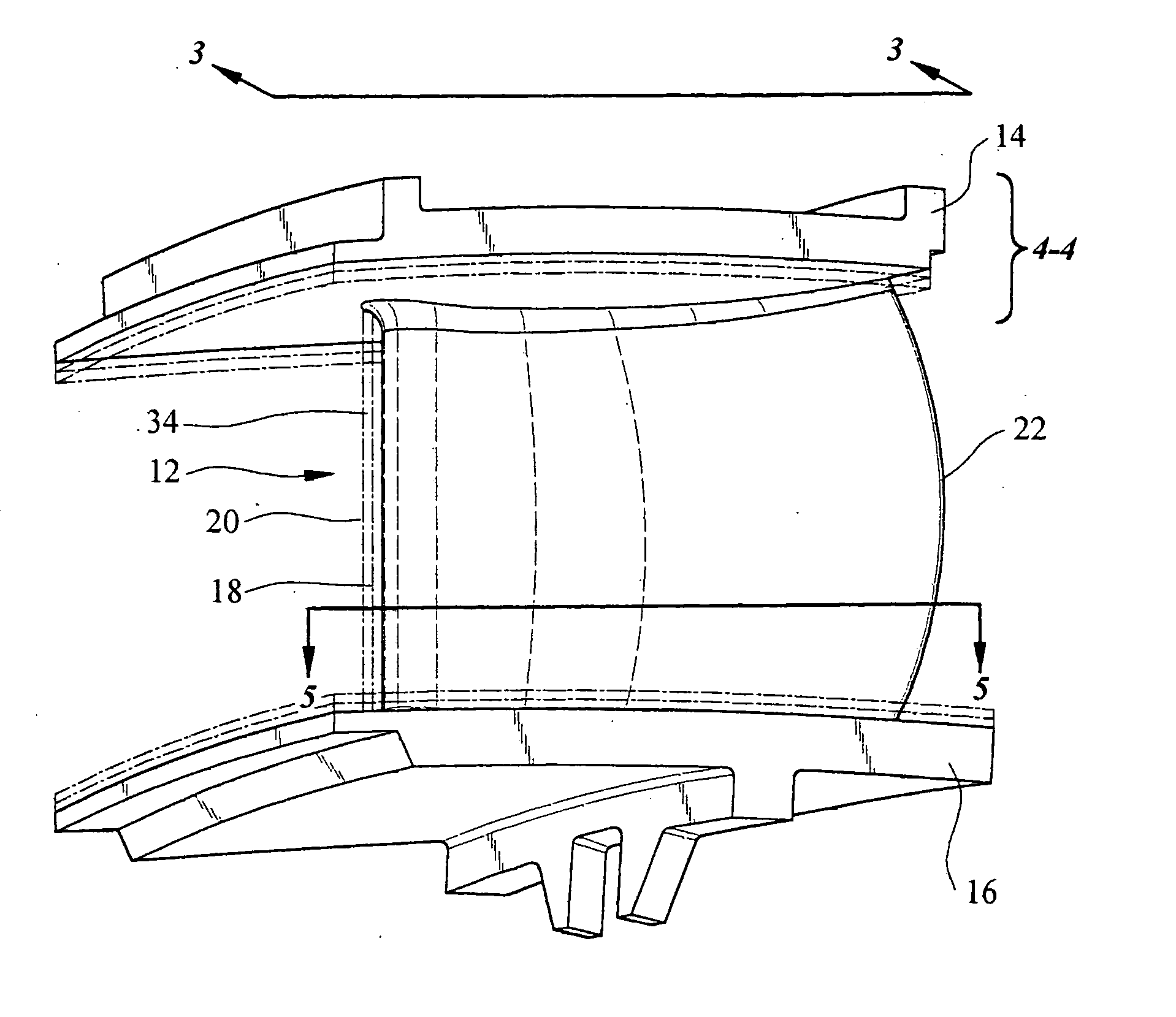
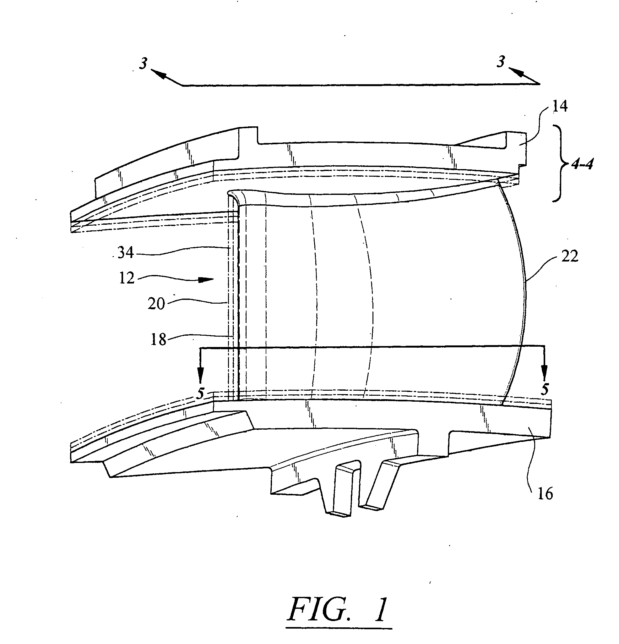
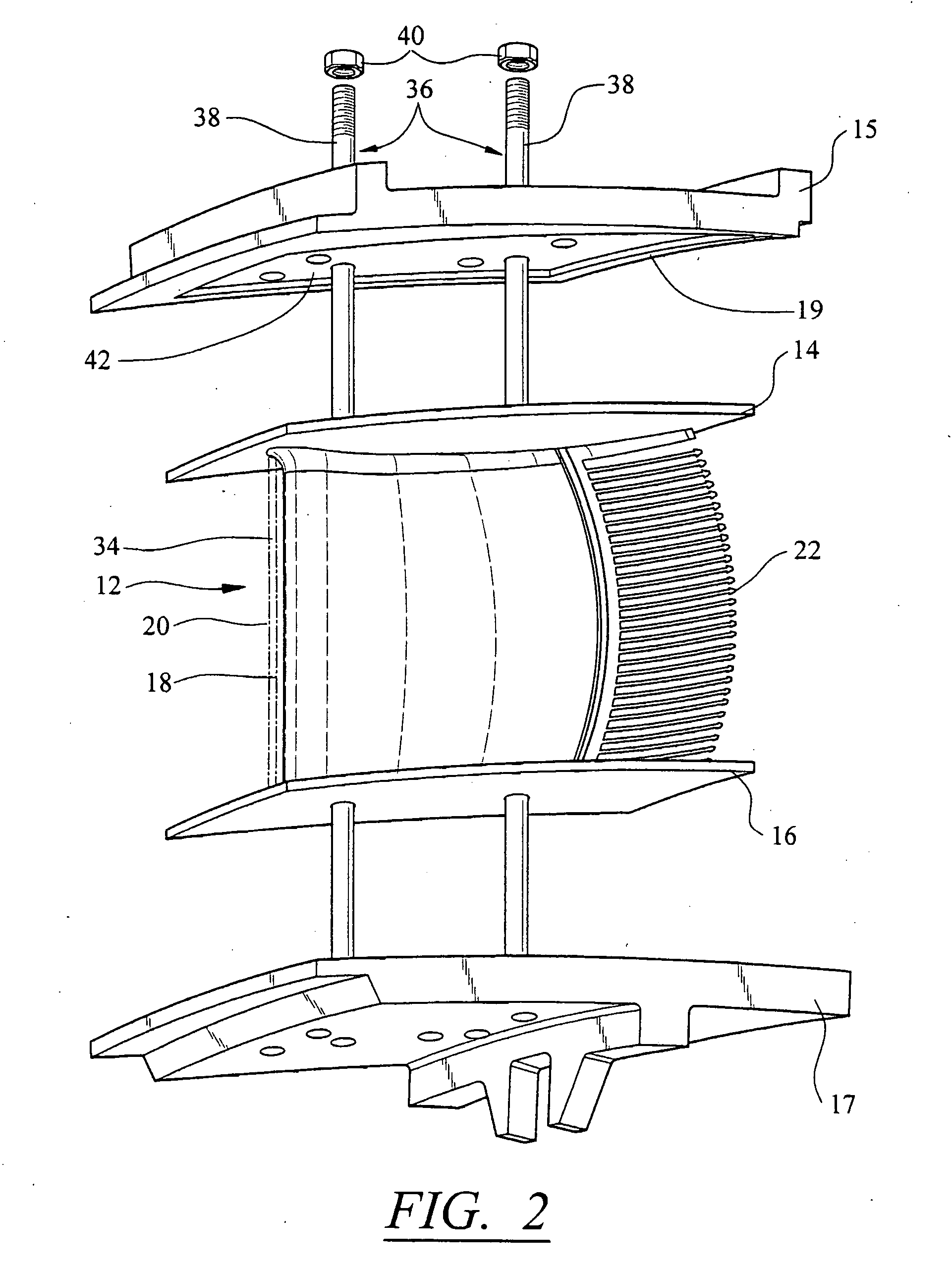
[0019] As shown in FIGS. 1-6, this invention is directed to a turbine airfoil support system 10 usable to provide support to composite turbine airfoils 12. In particular, the turbine airfoil support system 10 may be configured to attach a turbine airfoil 12 to adjacent outer and inner shrouds 15, 17 such that the airfoil 12 is subject to compression loads at a perimeter of the airfoil 12, thereby reducing stresses at the intersections between the airfoil 12 and having outer diameter (OD) platform 14 and an inner diameter (ID) platform 16. In at least one embodiment, the elongated airfoil 18 may be formed from a composite material. Application of compressive forces to the elongated airfoil 18 prolongs the life of the airfoil 18 by enhancing the ability of the airfoil 18 to absorb tensile forces encountered during turbine engine operation.

[0020] As shown in FIG. 5, the elongated airfoil 18 may be formed from a leading edge 20, a trailing edge 22, a pressure side 24, and a suction sid...


PUM


Abstract

A turbine airfoil support system for coupling together a turbine airfoil formed from two or more components, wherein the support system is particularly suited for use with a composite airfoil. In at least one embodiment, the turbine airfoil support system may be configured to attach shrouds to both ends of an airfoil and to maintain a compressive load on those shrouds while the airfoil is positioned in a turbine engine. Application of the compressive load to the airfoil increases the airfoil's ability to withstand tensile forces encountered during turbine engine operation.

Description

FIELD OF THE INVENTION [0001] This invention is directed generally to airfoils usable in turbine engines, and more particularly to support systems for airfoils formed from two or more components. BACKGROUND [0002] Typically, gas turbine engines include a compressor for compressing air, a combustor for mixing the compressed air with fuel and igniting the mixture, and a turbine blade assembly for producing power. Combustors often operate at high temperatures that may exceed 2,500 degrees Fahrenheit. Typical turbine combustor configurations expose turbine vane and blade assemblies, to these high temperatures. As a result, turbine airfoils, such as turbine vanes and blades must be made of materials capable of withstanding such high temperatures. In addition, turbine airfoils often contain internal cooling systems for prolonging the life of the airfoils and reducing the likelihood of failure as a result of excessive temperatures. [0003] Typically, turbine airfoils, such as turbine vanes ...

Claims


Application Information

Patent Timeline
Patent Type & Authority Applications(United States)
IPC IPC(8): F01D5/26
CPCF01D5/147F05D2230/64
Inventor ALBRECHT, HARRY A.SHTEYMAN, YEVGENIY
Owner SIEMENS ENERGY INC
Why Eureka
Try Eureka