
Linear compressor

Inactive Publication Date: 2006-08-03
FISHER & PAYKEL APPLIANCES LTD
View PDF86 Cites 28 Cited by
  • Summary
  • Abstract
  • Description
  • Claims
  • Application Information

AI Technical Summary

Benefits of technology

[0015] It is an object of the present invention to provide a compact linear compressor which goes some way to overcoming the abovementioned disadvantages.

Problems solved by technology

However, even in their most efficient form, there are significant losses associated with the crank system that converts rotary motion to linear reciprocating motion.
Alternatively a rotary compressor which does not require a crank can be used but again there are high centripetal loads, leading to significant frictional losses.
However with normal manufacturing tolerances and equipment production of effective gas bearings is difficult.
However this arrangement would be too complex and costly for use in a commodity item such as a domestic refrigerator.
However this approach limits the operation of the compressor because the counterweight is a negative feedback device and is limited to the fundamental unbalance force.
However in implementing this design in a domestic refrigerator there is a problem when the piston mass is low.
This is a problem because the “third” vibration mode (where the piston and the cylinder vibrate in phase with each other but out of phase with the compressor shell) is only slightly above the desirable “second” mode (where the shell does not vibrate and the piston and cylinder are out of phase).
It has been found that the edges cut in the pressing operation require careful polishing to regain the original strength of the spring steel sheet, and are frequently subject to failure through inadvertent stress concentrations.
A further problem of compressors generally has been the build up of heat, particularly in the vicinity of the compressor cylinder and the cylinder head.
The build up of heat creates significant problems of increased wear and of running conditions and tolerances between parts which vary according to the time period for which the compressor has been running.
This arrangement has the disadvantage of requiring an additional pump for forcing the liquid refrigerant through the cooling jacket surrounding the cylinder and subsequently into the exhaust manifold against the pressure of the compressed gas.
But conventional compressor dimensions constrain the size of the machinery compartment of a refrigerator and lead to wasted space in the compartment surrounding the compressor.

Method used


Image

  • Linear compressor
  • Linear compressor
  • Linear compressor

Examples


Embodiment Construction

General Configuration

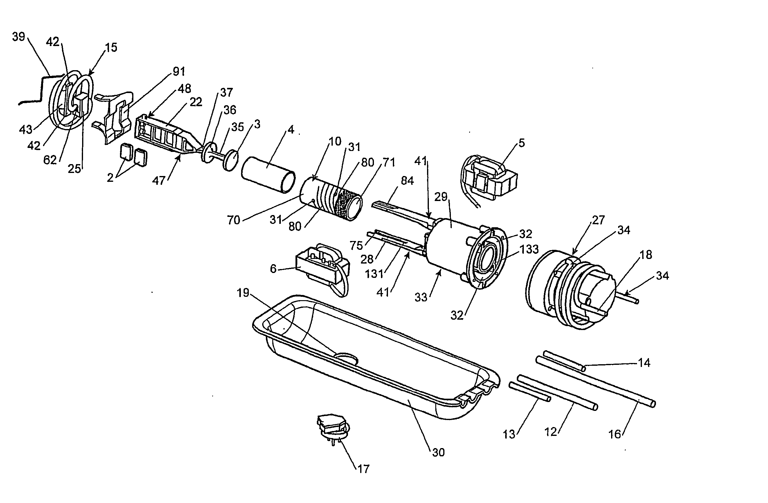
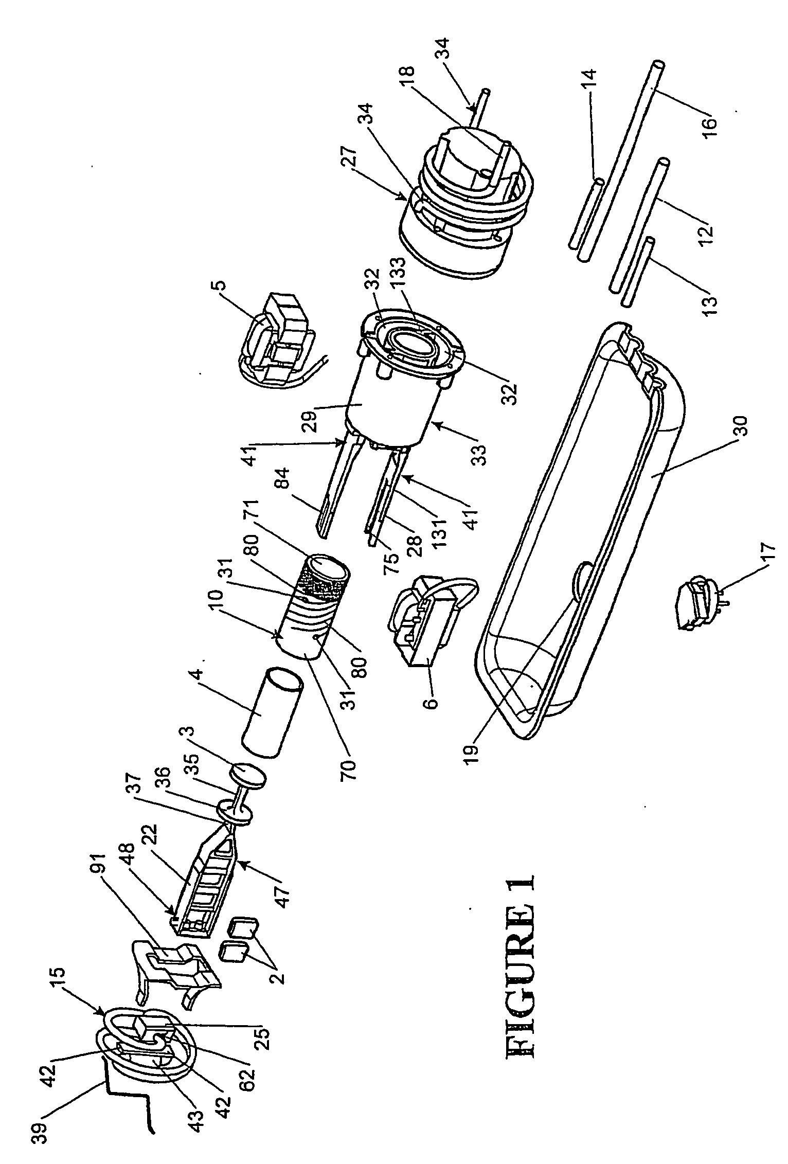
[0051] A practical embodiment of the invention, shown in the Figures, involves a permanent magnet linear motor driving a resonantly reciprocating compressor, together operating within a hermetic casing. The compressor includes a piston 3, 4 reciprocating within a cylinder bore 71 and operating on a working fluid which is alternately drawn into and expelled from a compression space at the head end of the cylinder. A cylinder head 27 connected to the cylinder encloses an open end of the cylinder bore 71 to form the compression space and includes inlet and outlet valves 118, 119 and associated manifolds. The compressed working gas exits the compression space through the outlet valve 119 into a discharge manifold. The discharge manifold channels the compressed working fluid into a cooling jacket 29 surrounding the cylinder 71. A discharge tube 18 leads from the cooling jacket 29 and out through the hermetic casing.

[0052] The cylinder 71 and jacket 29 are integral...


PUM

PropertyMeasurementUnit
Flexibilityaaaaaaaaaa
Widthaaaaaaaaaa
Fatigue strengthaaaaaaaaaa

Abstract

A linear compressor comprising has a cylinder part including a cylinder bore. A piston disposed in, and is slidable within, the bore. A main spring connects the cylinder part directly or indirectly the piston. A connecting rod connects between the main spring and the piston. A stator has an air gap, and the connecting rod passes through the air gap. At least one armature pole is located along the connecting rod. Other inventions are also set forth.

Description

[0001] This application is a divisional application of pending Ser. No. 10 / 399,314, which was accorded a filing date under 35 U.S.C. §371 of Apr. 16, 2003, and entitled Linear Compressor which is the National Stage of International Application No. PCT / NZ00 / 00201 which has an international filing date of Oct. 17, 2000 and which was published in English on May 2, 2002 under International Publication Number WO 02 / 35093.BACKGROUND TO THE INVENTION [0002] 1. Field of the Invention [0003] The present invention relates to a linear compressor, particularly but not solely for use in refrigerators. [0004] 2. Summary of the Prior Art [0005] Compressors, in particular refrigerator compressors, are conventionally driven by rotary electric motors. However, even in their most efficient form, there are significant losses associated with the crank system that converts rotary motion to linear reciprocating motion. Alternatively a rotary compressor which does not require a crank can be used but again ...

Claims


Application Information

Patent Timeline
IPC IPC(8): F04B17/00F01B23/08F04B35/04F16F1/06
CPCF04B35/045F16F1/06Y10T29/49238Y10T29/4984Y10T29/49236H02K33/16F04B17/04F25B31/023
Inventor SEAGAR, NEVILLE DAVIDMCGILL, IAN CAMPBELLDUNCAN, GERALD DAVIDPATEL, UPESHTAYLOR, ANDREW PAULLEE, GEOFFREY ALAN
Owner FISHER & PAYKEL APPLIANCES LTD
Features
  • Generate Ideas
  • Intellectual Property
  • Life Sciences
  • Materials
  • Tech Scout
  • Unparalleled Data Quality
  • Higher Quality Content
  • 60% Fewer Hallucinations
Learn More