Multi-array, multi-specific electrochemiluminescence testing

a multi-specific, electrochemiluminescence technology, applied in the direction of instruments, material electrochemical variables, biomass after-treatment, etc., can solve the problems of radioactive labeling, high sensitivity of certain diagnostic technologies, and insufficient robustness for various markets,

a multi-specific, electrochemiluminescence technology, applied in the direction of instruments, material electrochemical variables, biomass after-treatment, etc., can solve the problems of radioactive labeling, high sensitivity of certain diagnostic technologies, and insufficient robustness for various markets,

US20060172340A1Inactive Publication Date: 2006-08-03MESO SCALE TECH LLC

Image

  • Multi-array, multi-specific electrochemiluminescence testing
  • Multi-array, multi-specific electrochemiluminescence testing
  • Multi-array, multi-specific electrochemiluminescence testing

Examples


Embodiment Construction

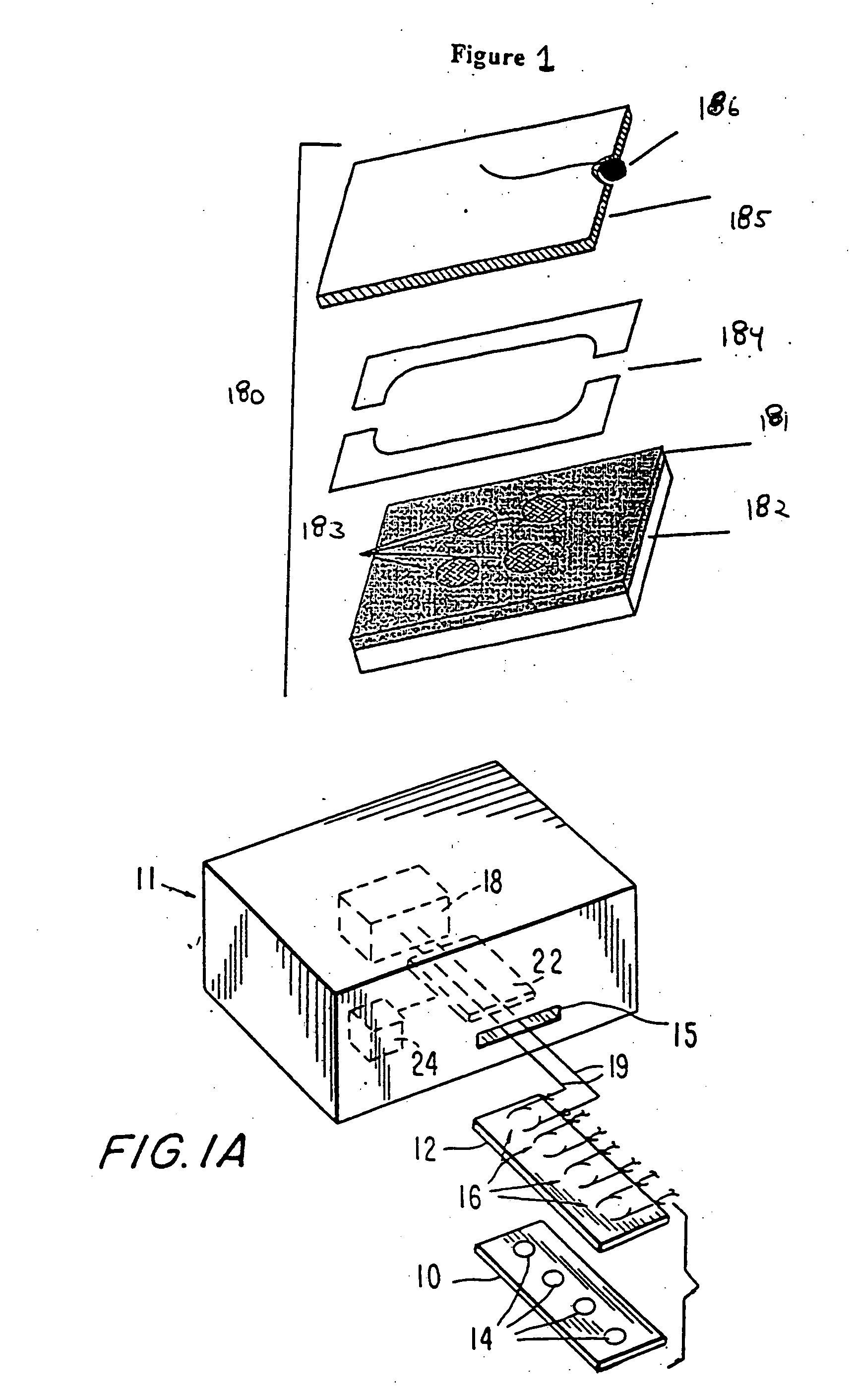
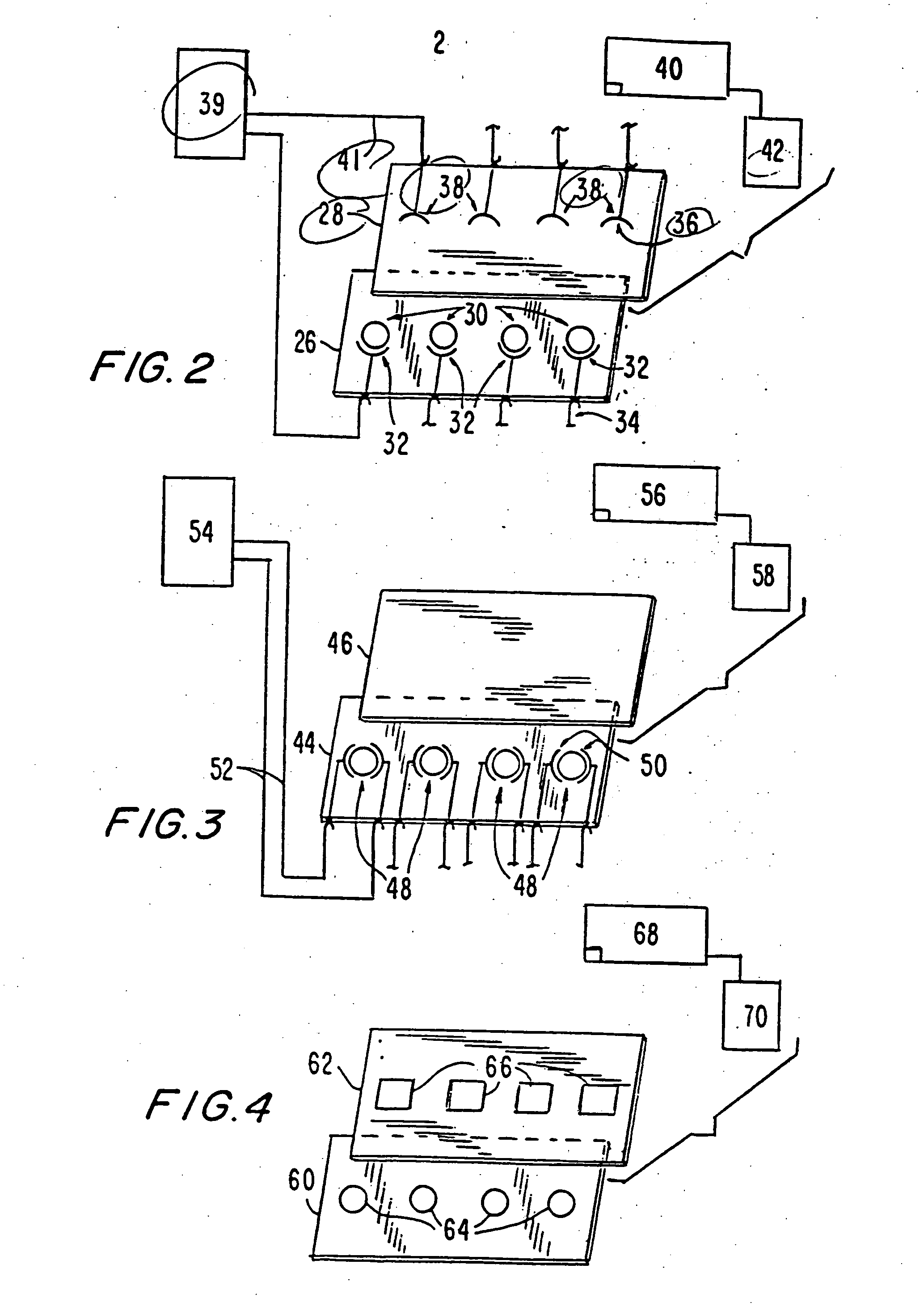
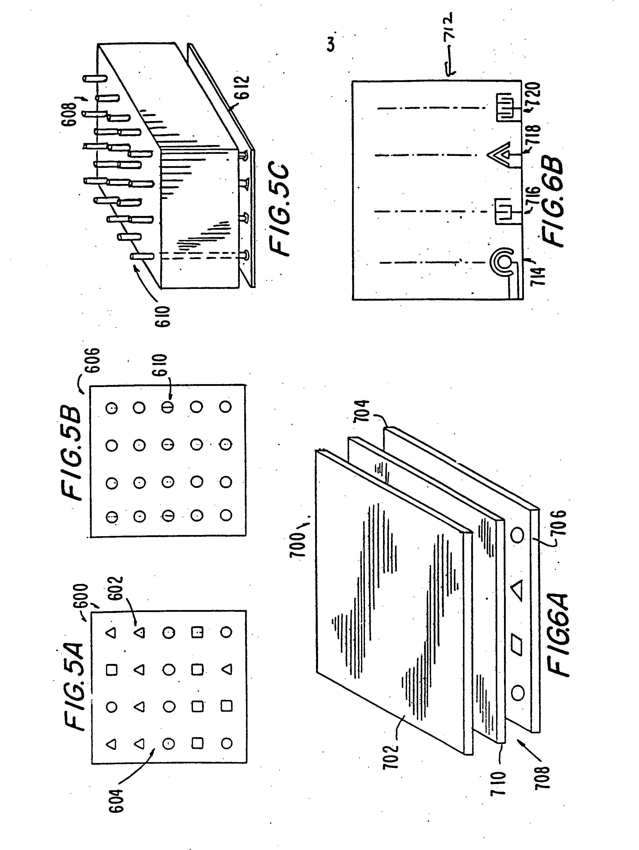
[0105] Accordingly, the invention includes in a broad aspect cassettes for conducting one or more electrochemiluminescence assays. The cassettes are formed of supports having thereon a plurality of binding domains able to specifically bind one or more analytes of interest. The binding domains are prepared as patterned, multi-array multi-specific surfaces (“PMAMS”) on the support. The PMAMS offer a significant improvement from ECL assay methods previously known by, e.g., greatly increasing the density of assays that can be performed and allowing for a plurality of different assays that may be rapidly or simultaneously performed.

[0106] The cassette may include a plurality of electrodes able to selectively trigger ECL emission of light from ECL labeled reagents bound to the binding domains. FIG. 47 shows an multi-array ECL apparatus using a cassette 4700 which comprises a housing 4717, electrical connections to the electrode in the cassette 4718, a waveform generator or potentiostat 4...


PUM

PropertyMeasurementUnit
areaaaaaaaaaaa
molar concentrationsaaaaaaaaaa

Abstract

Materials and methods are provided for producing patterned multi-array, multi-specific surfaces for use in diagnostics. The invention provides for electrochemiluminescence methods for detecting or measuring an analyte of interest. It also provides for novel electrodes for ECL assays. Materials and methods are provided for the chemical and / or physical control of conducting domains and reagent deposition for use multiply specific testing procedures.

Description

[0001] This application is a continuation-in-part of copending application Ser. No. 08 / 611,804 filed Mar. 6, 1996, which is a continuation-in-part of copending application Ser. No. 08 / 402,076 filed Mar. 10, 1995 and Ser. No. 08 / 402,277 filed Mar. 10, 1995, each of which is incorporated by reference herein in its entirety.1. INTRODUCTION [0002] The present invention provides for a patterned multi-array, multi-specific surface (PMAMS) for electrochemiluminescence based tests, as well as methods for making and using PMAMS. 2. BACKGROUND OF THE INVENTION [0003] 2.1. Diagnostic Assays [0004] There is a strong economic need for rapid sensitive diagnostic technologies. Diagnostic technologies are important in a wide variety of economic markets including health care, research, agricultural, veterinary, and industrial marketplaces. An improvement in sensitivity, time required, ease of use, robustness, or cost can open entirely new diagnostic markets where previously no technology could meet ...

Claims


Application Information

Patent Timeline
03 Aug 2006
Publication
US20060172340A1
IPC
G01N33/53; C12M1/34; C12M1/00; G01N33/536; C12Q1/00; G01N21/00; G01N21/66; G01N21/76; G01N27/30; G01N27/327; G01N27/416; G01N33/533; G01N33/543; G01N33/566; G01N33/58
CPC
B82Y15/00; B82Y30/00; G01N21/66; G01N21/76; G01N33/54313; G01N33/5438; G01N33/582; G01N33/585
Inventors
WOHLSTADTER, JACOB N.; WILBUR, JAMES