Electromagnetically tracked K-wire device

a technology of k-wire and k-wire, which is applied in the field of k-wire devices, can solve the problems of difficult to track the distal end of the k-wire, the general ability of the optical tracking system to effectively track the tip, etc., and achieve the effect of effectively tracking the tip, reducing the use of intra-operative x-rays, and increasing accuracy

Inactive Publication Date: 2006-08-03
PHILIPS ELECTRONICS LTD
View PDF99 Cites 187 Cited by
  • Summary
  • Abstract
  • Description
  • Claims
  • Application Information

AI Technical Summary

Benefits of technology

[0012] One aspect of the invention relates to a method for directly tracking the tip of the K-wire (e.g., electromagnetically). Among other things this may provide a significant improvement and can lead to increased accuracy and decreased use of intra-operative X-rays. In contrast, optical tracking systems generally are not capable of effectively tracking the tip since they are typically limited to line of sight applications. This makes it difficult for them to track the distal end of the K-wire that is implanted in the patient. The electro-magnetically tracked K-wires would offer a dramatic reduction in surgical invasiveness as compared with current CAS procedures. They would be compatible with existing CAS modalities including conventional (point match registration), virtual fluoroscopy and 2D-3D. In addition to aiding in cannulating the pedicle, a tracked K-wire could potentially assist in other aspects of the current technique including registration, dynamic referencing and verification of registration.

Problems solved by technology

In contrast, optical tracking systems generally are not capable of effectively tracking the tip since they are typically limited to line of sight applications.
This makes it difficult for them to track the distal end of the K-wire that is implanted in the patient.

Method used


Image

  • Electromagnetically tracked K-wire device
  • Electromagnetically tracked K-wire device
  • Electromagnetically tracked K-wire device

Examples


Embodiment Construction

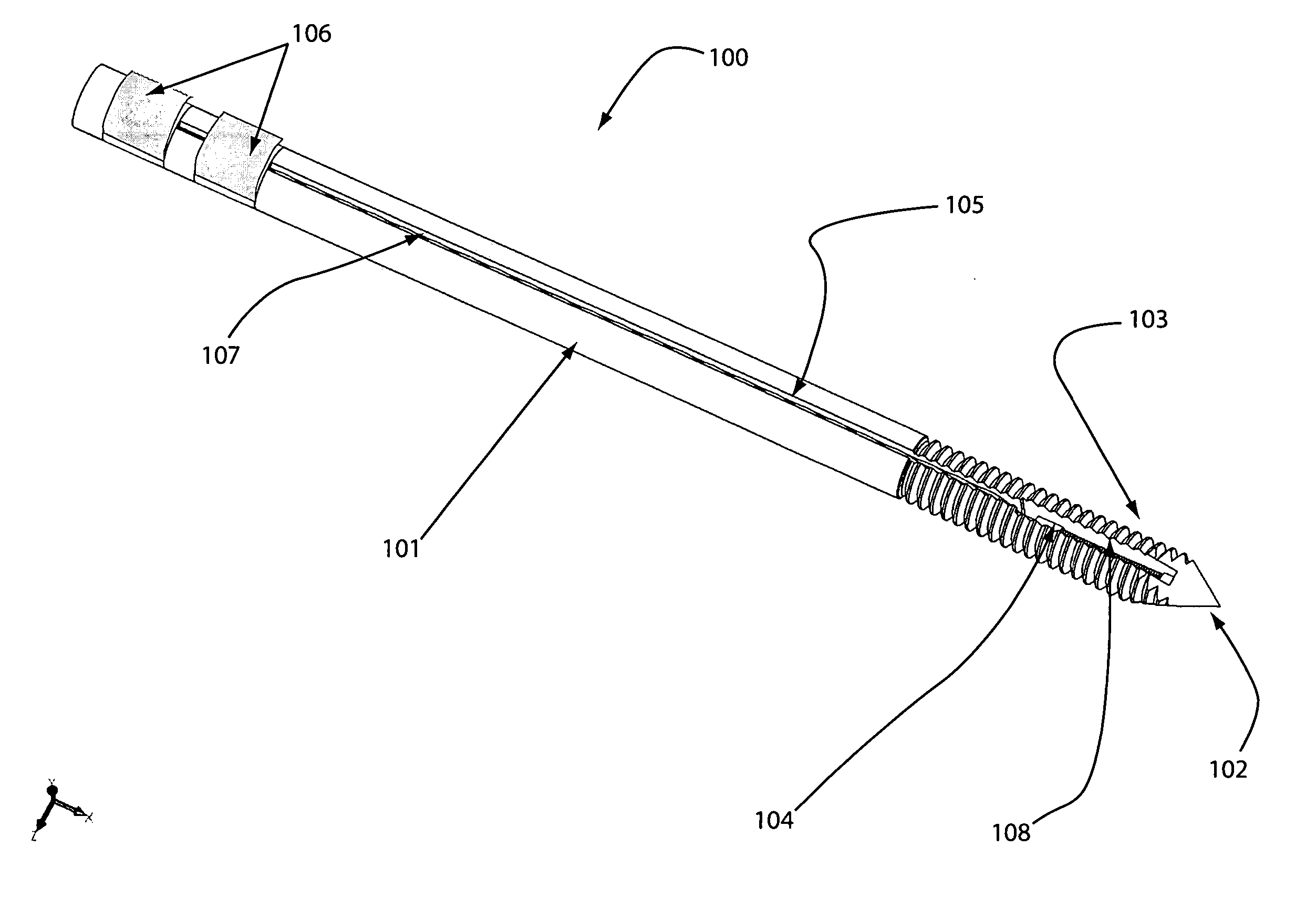
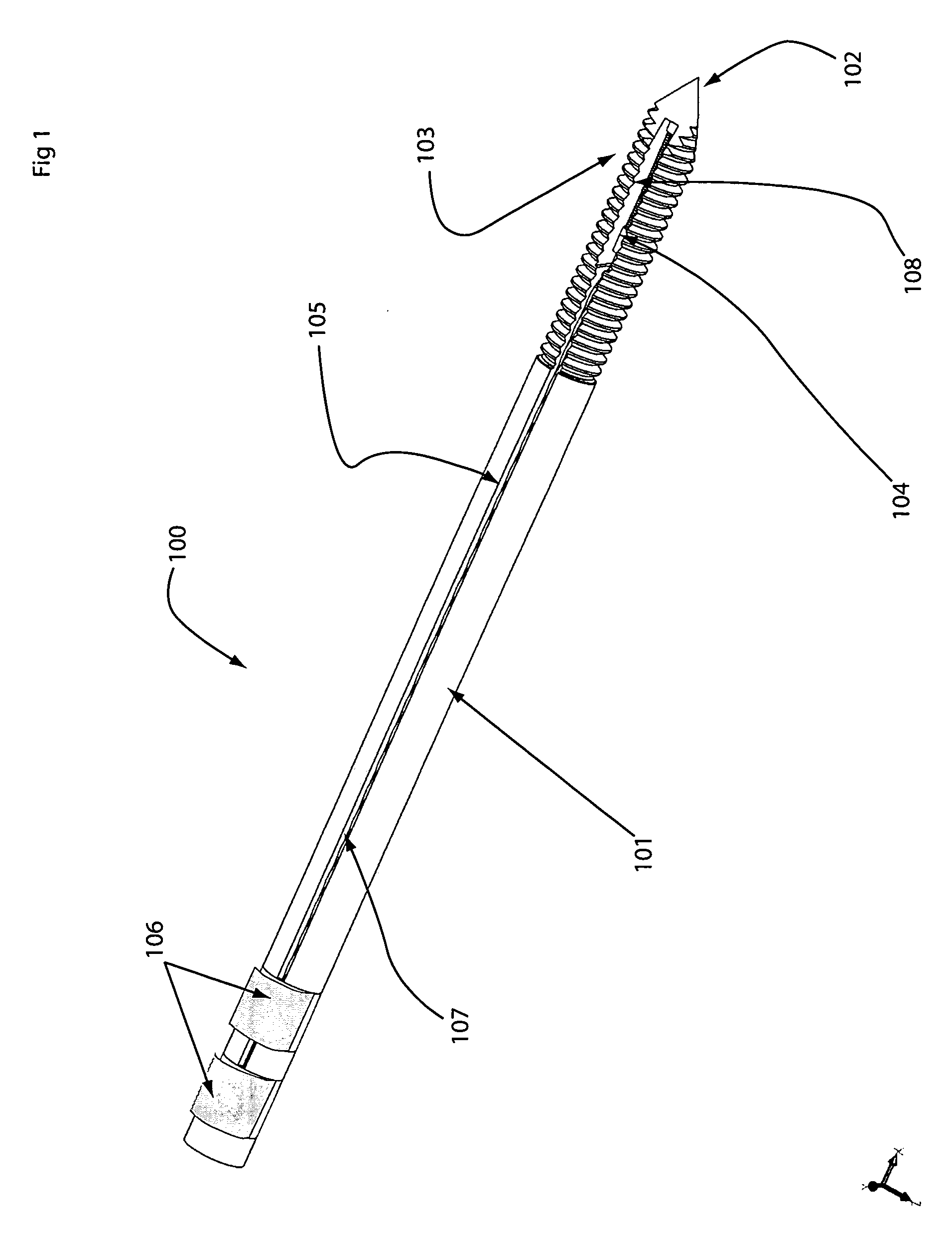
[0027] One embodiment of the invention is shown by way of example in FIG. 1. As shown, the device includes a K-wire 100 comprised of a shaft section 101, a tip section 102, and an optionally threaded portion 103, along all or part of its length. The K-wire contains at least one electromagnetically tracked position-indicating element 104 embedded near its tip. The lead-wires 105 of the position-indicating element are connected to connection bands 106, which may be coated with gold or other suitable conductive coating. The connection bands may be placed at the proximal end of the K-wire or otherwise.

[0028] To facilitate placement of the position-indicating element and wiring, a groove 107 may be machined along all or part of the length of the K-wire. The tip 102 is preferentially made sharp, for example as a trocar 3 point tip. Likewise, the position-indicating element 104 can be embedded into a groove 107, machined into the tip of the K-wire.

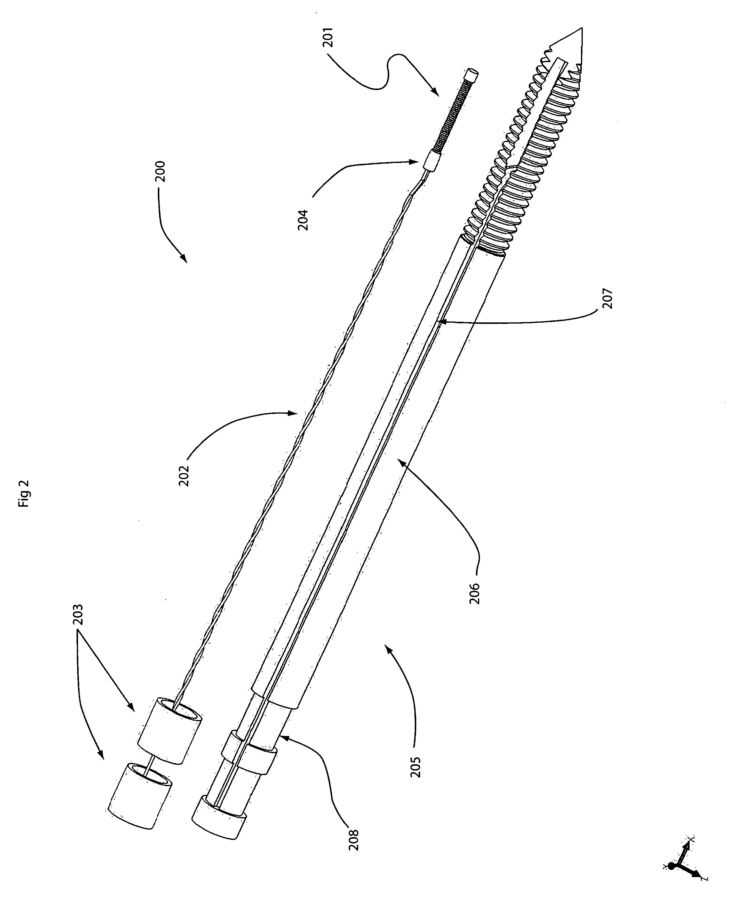
[0029]FIG. 2 depicts an exploded view of...


PUM


Abstract

Devices and methods for registering, dynamically referencing, and navigating an anatomical region of interest of a patient are provided using a tracked Kirschner wire (K-wire), where the K-wire includes a position-indicating element.

Description

RELATED APPLICATIONS [0001] This application claims priority to U.S. Provisional Patent Application Ser. No. 60 / 644,007, filed Jan. 18, 2005, which is hereby incorporated by reference herein in its entirety.FIELD OF THE INVENTION [0002] The invention relates to electromagnetically tracked K-wire devices. BACKGROUND OF THE INVENTION [0003] Image-guided surgery systems use a position sensor system to graphically overlay an iconic representation of a tracked surgical instrument onto pre-acquired images (e.g., CT, MR, fluoroscopic X-ray or other images) of the patient. Current state of the art tracking employs optical systems characterized by a high degree of accuracy. However, the ergonomics of these systems are poor, and optical systems require that tracked objects remain in the camera's line of sight, relatively distant from the instrument tip. The relatively heavy and large position-indicating elements must be attached to rigid instruments to achieve the required accuracy. In partic...

Claims


Application Information

Patent Timeline
Patent Type & Authority Applications(United States)
IPC IPC(8): A61B5/05
CPCA61B2017/0046A61B2090/3983A61B90/96A61B90/36A61B2090/3975A61B90/94A61B90/98A61B34/20A61B2034/2051A61B90/39
Inventor GLOSSOP, NEIL
Owner PHILIPS ELECTRONICS LTD
Why Eureka
Try Eureka