Insertion device

a technology of insertion device and insertion needle, which is applied in the direction of catheters, other medical devices, needles infusion, etc., can solve the problems of cumbersome assembling process, and increased risk of needle pricks in the assembling process, so as to facilitate the pressure of the collapse part, improve the grip of the user, and improve the effect of handling

Active Publication Date: 2006-08-03
MEDTRONIC MIMIMED INC
View PDF99 Cites 179 Cited by
  • Summary
  • Abstract
  • Description
  • Claims
  • Application Information

AI Technical Summary

Benefits of technology

[0014] In the embodiment, other safety features may be included. For example, a needle notch can be placed inside the hub on the end wherein the needle tip is directed by the guard part. The needle notch includes a block that keeps the needle tip in place. The needle notch further ensures that there cannot be unintended contact with the needle tip.
[0015] In another embodiment of the invention, a hub removably attachable to the base of a cannula housing of an infusion set may include a handle part and a guard part, with a collapse part on one side of the hub and a guard part on the opposite side. The collapse part is attached to a push block within the hub. The collapse part is an area on the hub that can flex and collapse inwards when pressure is added. The collapse part may be composed of any suitable material that will allow it to be flexed without fracturing. The opposing walls of the collapse part are biased to improve the wall collapse when pressure is applied. This inward collapse of the walls facilitate the pressure of the collapse part on the push block. The collapse part causes the push block to flex in towards the needle housing, where the needle resides, pushing the needle so that it bends up into the guard part. The guard part may be extended to receive and cover the needle, with the guard part having a needle recess on its underside wherein the needle is received. Catches may be positioned on opposing sides of the inside of the hub to lock the needle within the guard part. When the walls collapse inward, the catches connect and hold the walls in the collapsed position. The needle, which is pushed into the needle recess, is held and secured inside the guard part in that position. The catches prevent the needle from leaving the guard part once it is pushed into the needle recess of the guard. This locked position may be temporary or permanent. As another alternative, the needle may be secured within the guard part by alternative locking structures to catches, such as hooks, ba

Problems solved by technology

While this allows for increased mobility, there remain disadvantages to patients for other reasons.
Therefore, upon withdrawal of an insertion device from the base, there are potential risks of unintended harm from the sharp end to the user or others.
While some insertion devices in the art provide ways to cover the exposed needle

Method used


Image

  • Insertion device
  • Insertion device
  • Insertion device

Examples


Embodiment Construction

[0042] In the following description, reference is made to the accompanying drawings which form a part hereof and which illustrate several embodiments of the present invention. It is understood that other embodiments may be utilized and structural and operational changes may be made without departure from the scope of the present invention.

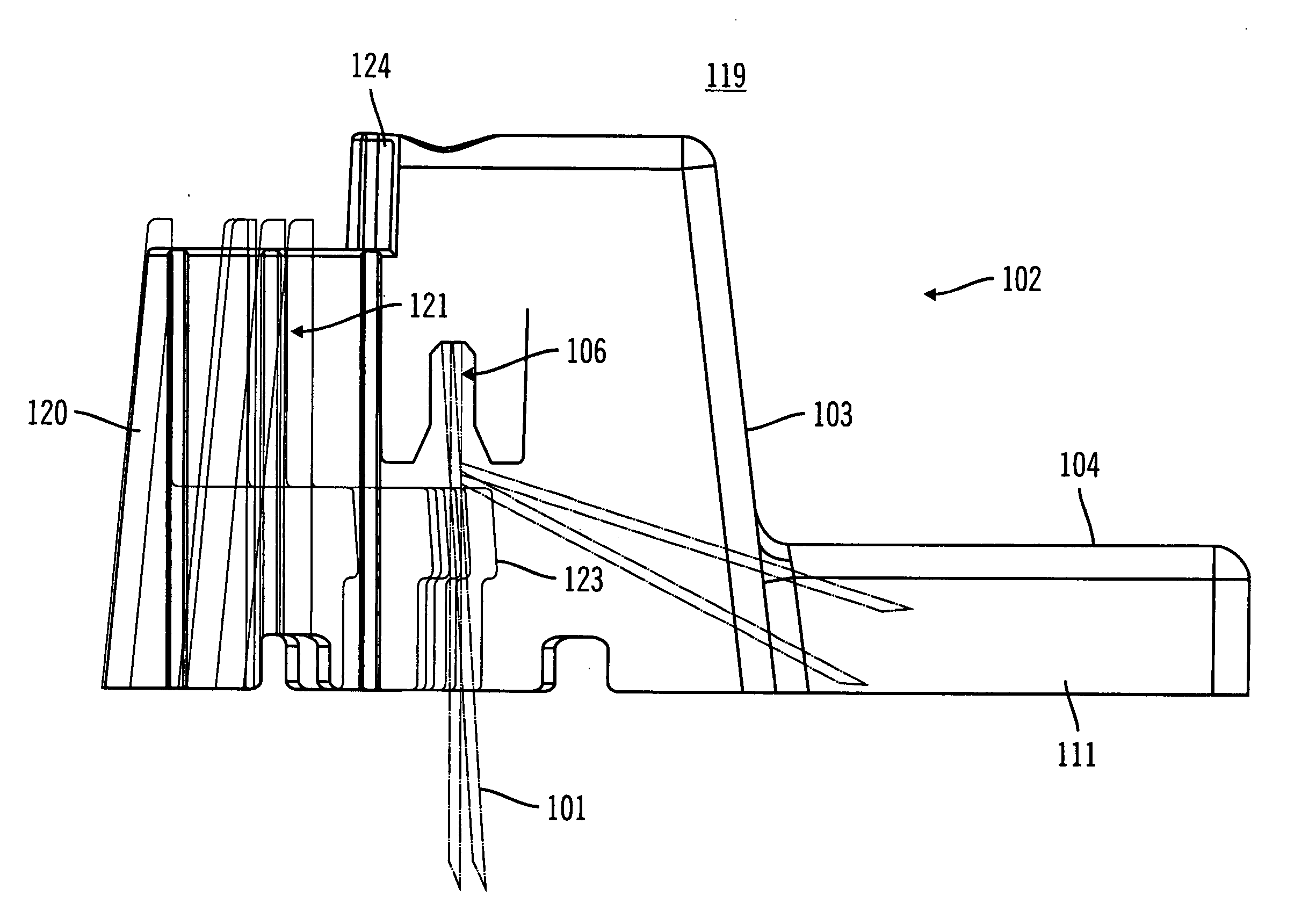
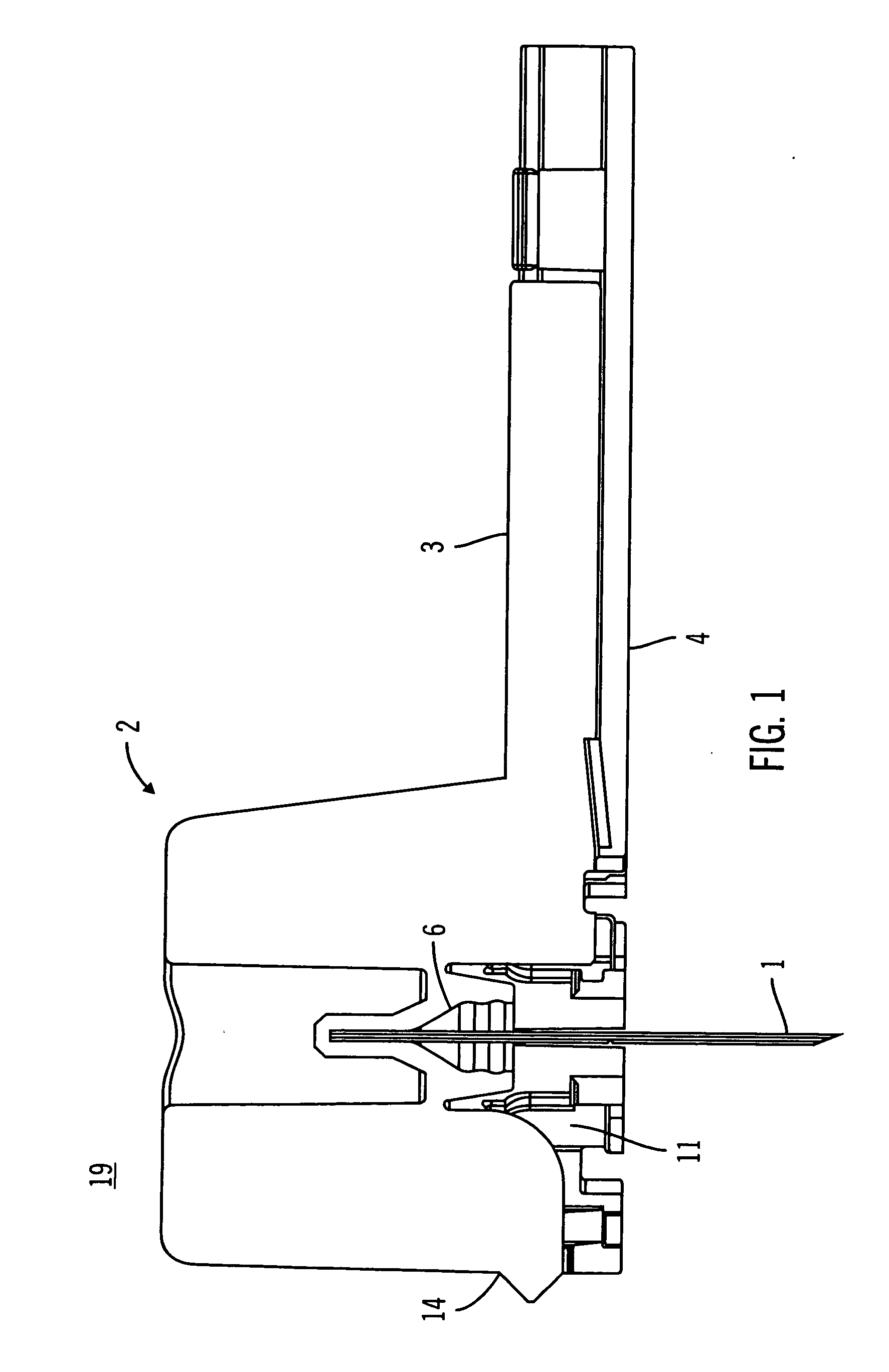
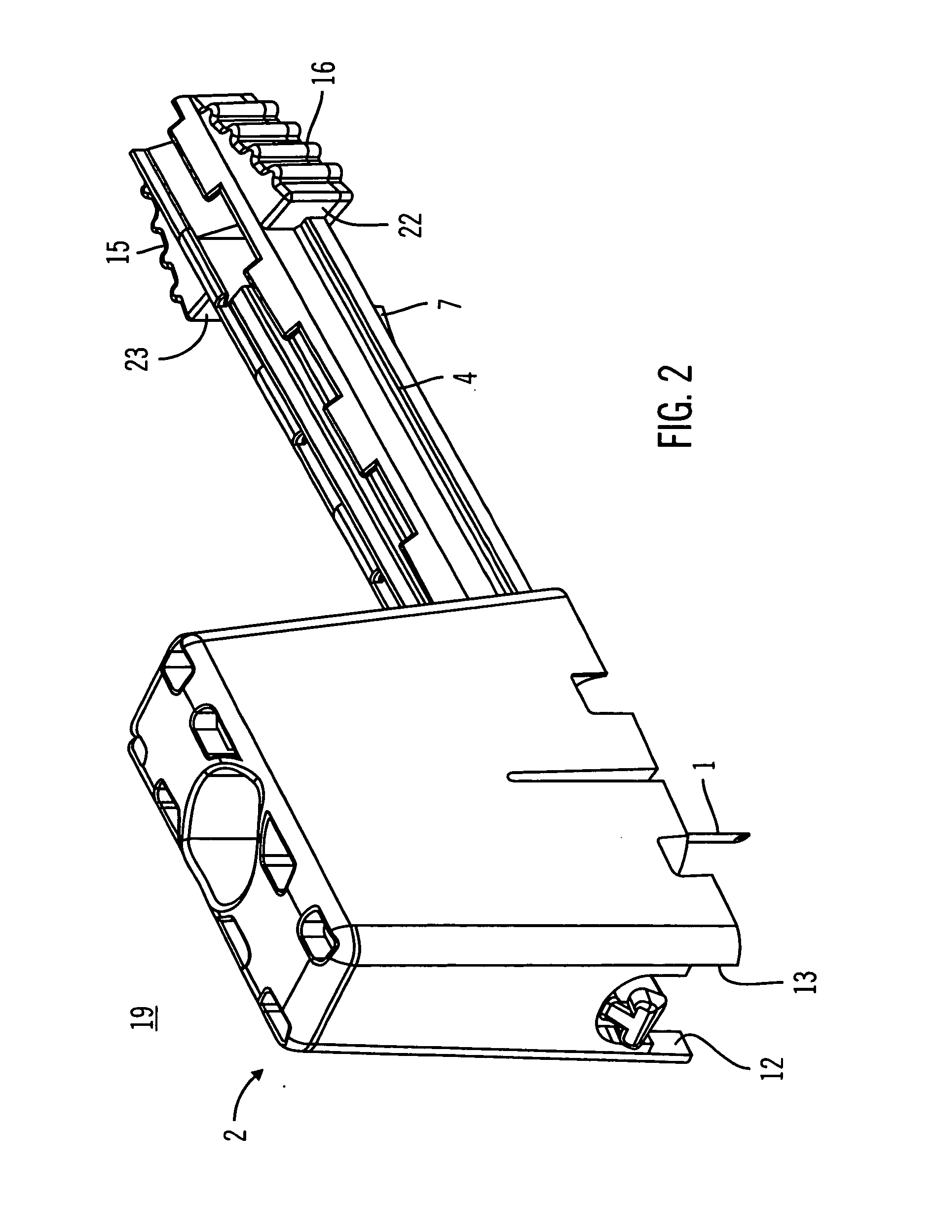
[0043] In FIG. 1, the insertion device shown schematically by the reference numeral 19 includes a hub 2 having thereon an insertion needle 1. The needle 1 is held in place by a needle housing 6 within the hub 2. The needle 1 on the end opposite to the hub 2 is pointed or as otherwise to facilitate puncturing. The hub 2 includes a guard part 4 and a handle part 3. Along the outer end of the handle part 3, the guard part 4 is capable of slidably moving along the handle part 3. In one alternative, the handle part 3 protrudes from the hub 2 and is tubular in shape. The handle part 3 may include a pocketed cross-section that forms a needle recess (not ...


PUM


Abstract

An insertion device, generally used with an infusion set, including a needle being adapted for puncturing at one end and including at the opposite end a hub. The hub includes a handle part and a guard part that are capable of securing the needle through the use of locks. Locking structures are used to secure the insertion device in a position where the needle is covered in a locked position, avoiding unintended contact with the needle.

Description

BACKGROUND OF THE INVENTION [0001] 1. Field of Invention [0002] Embodiments of the present invention relate generally to an insertion device used commonly for subcutaneously puncturing a site in a patient to insert a soft cannula that forms part of an infusion set for subcutaneous delivery of a fluid, drug or other infusant by means of an external infusion system. More particularly, embodiments of the invention relate to an insertion device capable of being disposed of without the risks of causing unintended harmful injuries to persons. [0003] 2. Description of Related Art [0004] Insertion devices are generally used in the field of subcutaneous infusion sets. These infusion sets are used for delivering a fluid, medication or other infusant, for example, insulin, to a subcutaneous site in a patient. Such an infusion set is described, for example, in U.S. Pat. Nos. 6,520,938 and 6,056,718, which are herein incorporated by reference. Another example is described in co-pending U.S. appl...

Claims


Application Information

Patent Timeline
IPC IPC(8): A61M5/00
CPCA61M5/3216A61M5/3243A61M25/02A61M25/0612A61M5/158A61M2005/1583A61M2005/1585A61M2025/028A61M2005/1581
Inventor MOBERG, SHELDON B.MAULE, SUSIE E.HOLT, MARK D.CHENEY, PAUL S. IIHOLECEK, ARIN N.GRIFFIN, CHRISTOPHER G.KAVAZOV, JULIAN D.
Owner MEDTRONIC MIMIMED INC
Why Eureka
Try Eureka