Flexible cells for interconnecting stent components

a flexible, stent technology, applied in the field of stents, to achieve the effect of low surface area, efficient and easy production, and absence of potential tissu

Inactive Publication Date: 2006-08-03
STENT TECH
View PDF2 Cites 46 Cited by
  • Summary
  • Abstract
  • Description
  • Claims
  • Application Information

AI Technical Summary

Benefits of technology

[0018] The stents of the present invention are expandable, typically, for example, by enlarging an expandable balloon positioned within the stent, which preferably comprises a plurality of expandable modules, such as a plurality of expandable ring structures. The ring structures are joined to one another by means of flexible interconnecting cells or interconnects, as described above. The stents feature an absence of potential tissue snagging structures. The ring structures can articulate with respect to one another, which enables the stent to pass through otherwise tortuous passageways

Problems solved by technology

However, in contrast to the closed cell design of stents, the flexible interconne

Method used


Image

  • Flexible cells for interconnecting stent components
  • Flexible cells for interconnecting stent components
  • Flexible cells for interconnecting stent components

Examples


Embodiment Construction

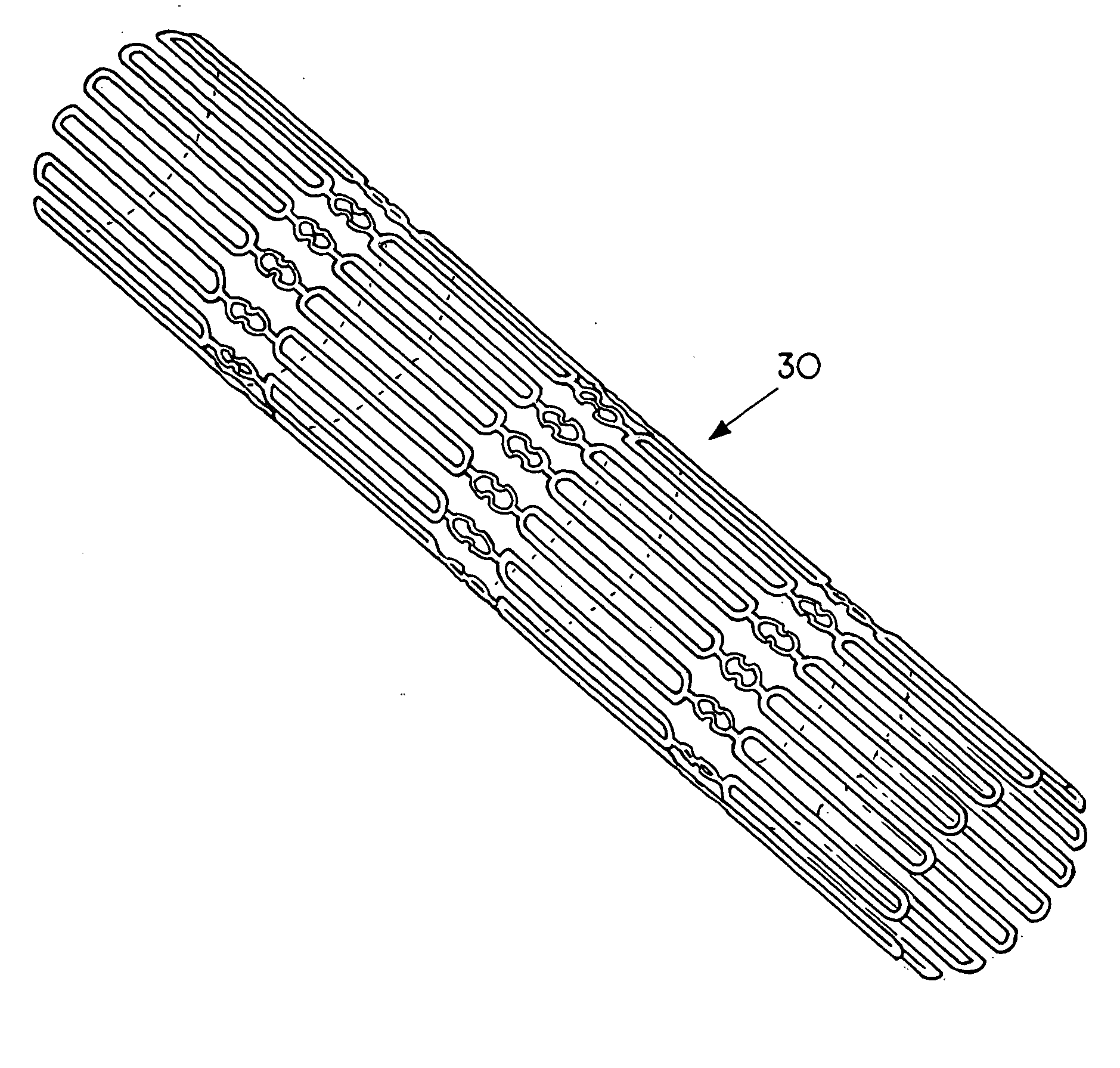
[0033] An expandable stent 30 according to the present invention is shown in FIG. 1.

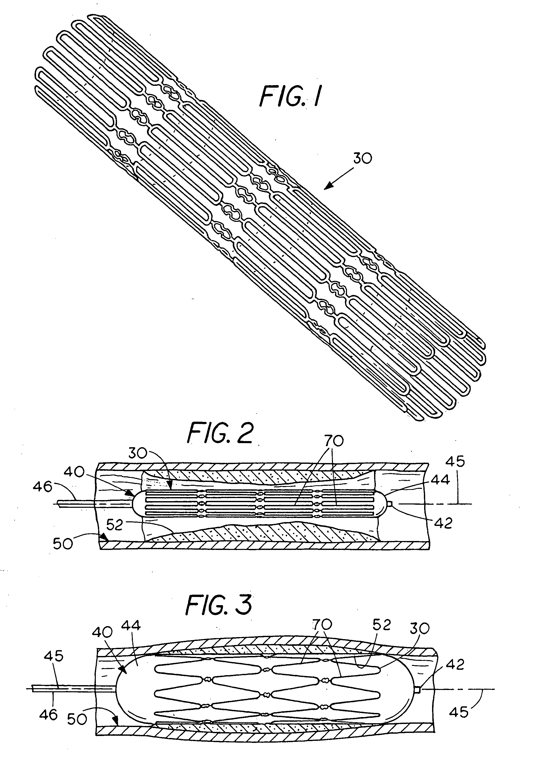
[0034] In FIG. 2 the stent 30 is shown as being temporarily fitted upon or generally coaxial with a balloon catheter 40, having a distal end 42, an expandable balloon 44, and a catheter shaft 46. The stent 30 is also shown closely associated within a portion of an artery 50, which is partially occluded by a stenosis 52.

[0035] As shown schematically in FIG. 3, once the stent 30 is appropriately located in the lumen of the artery 50, preferably spanning the stenosis 52, the stent 30 can be expanded outward radially by inflating the balloon 44 of the balloon catheter 40. Inflation of balloon 44 is accomplished by application of fluid pressure to its interior by the cardiologist, acting at the proximal end (not shown) of catheter 40 in a manner which is well known in the art. As balloon 44 expands, stent 30 is also expanded outward radially. As the expansion continues, the stent 30 and balloon 44 conta...


PUM


Abstract

Axially flexible stents for tracking through tortuous segments of tubular structures in body passages are disclosed. The stents, which utilize flexible interconnects, conform to such tortuous segments, track easily, and have sufficient surface areas to prevent gaps between stent components. In a preferred embodiment the interconnects have the form of “closed cells”. However, in contrast to stents of a closed cell design, the interconnects do not expand upon radial expansion of the stent during deployment. Instead, the interconnects can expand or contract axially to enable negotiating twists and turns encountered in body passageways. If the stent encounters a concavity in a body passageway, the interconnects contract. If the stent encounters a convexity, the interconnects expand.

Description

BACKGROUND OF THE INVENTION [0001] 1. Field of the Invention [0002] The present invention relates to medical devices and, more particularly, to stents that can be expanded for purposes of deployment. [0003] 2. Background of the Related Art [0004] Under normal circumstances, the heart functions as a pump to perfuse blood throughout the body through arteries. The arteries of some patients are subject to stenosis, a localized partial blockage, which narrows the passageway and interferes with normal blood flow. This condition is termed atherosclerotic coronary artery disease. It is a leading cause of morbidity in adults in the western world. One corrective procedure used to treat this disease is coronary bypass surgery, which is a highly invasive operation. In recent years a corrective procedure, percutaneous transluminal coronary angioplasty, and devices known as balloon angioplasty catheters have been widely used to correct stenotic conditions within arteries, particularly coronary ar...

Claims


Application Information

Patent Timeline
IPC IPC(8): A61F2/90
CPCA61F2/91A61F2/915A61F2230/0054A61F2002/91558A61F2002/91541
Inventor DAS, GLADWIN S.
Owner STENT TECH
Why Eureka
Try Eureka