Frequency integrator with digital phase error message for phase-locked loop applications

a phase-locked loop and frequency integrator technology, applied in the field of digital communication, can solve the problems of high power consumption of fine resolution tdc, in-band modulation noise, and approach that requires additional power consumption and ic die area, and achieves power-efficient high-performance digital plls and reduce power consumption. , the effect of improving the performance-to-power dissipation ratio of td

Active Publication Date: 2012-09-11
MACOM CONNECTIVITY SOLUTIONS LLC
View PDF7 Cites 6 Cited by
  • Summary
  • Abstract
  • Description
  • Claims
  • Application Information

AI Technical Summary

Benefits of technology

[0011]Disclosed herein are a system and method for converting a digital word, representing the phase offset between reference and phase-locked loop (PLL) synthesizer clocks, to a digital phase error word. A Successive Time to Digital Converter (STDC) processes the reference clock and frequency synthesizer clock, and generates a digital word representing the ratio of the two clock cycles, from which a digital represen

Problems solved by technology

This divider modulation produces in-band modulation noise and requires PLL bandwidth to be low to filter out the in-band noise.
One way of converting an analog signal to a digital signal is to utilize an analog-to-digital converter (A/D), but this approach requires additional power consumption and IC die area.
A key implementation challenge with the use of a TDC is the achiev

Method used


Image

  • Frequency integrator with digital phase error message for phase-locked loop applications
  • Frequency integrator with digital phase error message for phase-locked loop applications
  • Frequency integrator with digital phase error message for phase-locked loop applications

Examples


Embodiment Construction

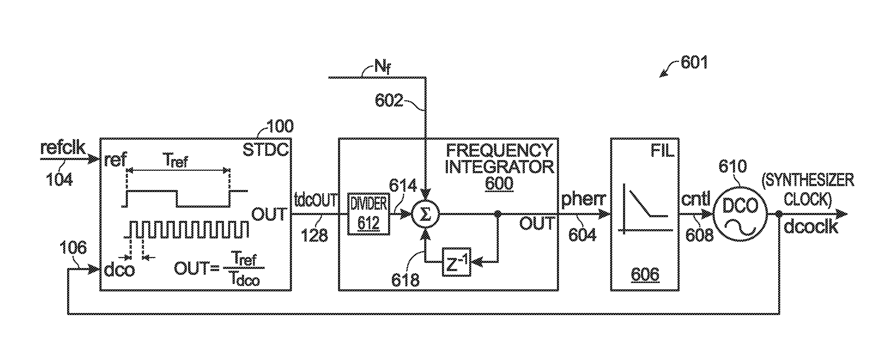
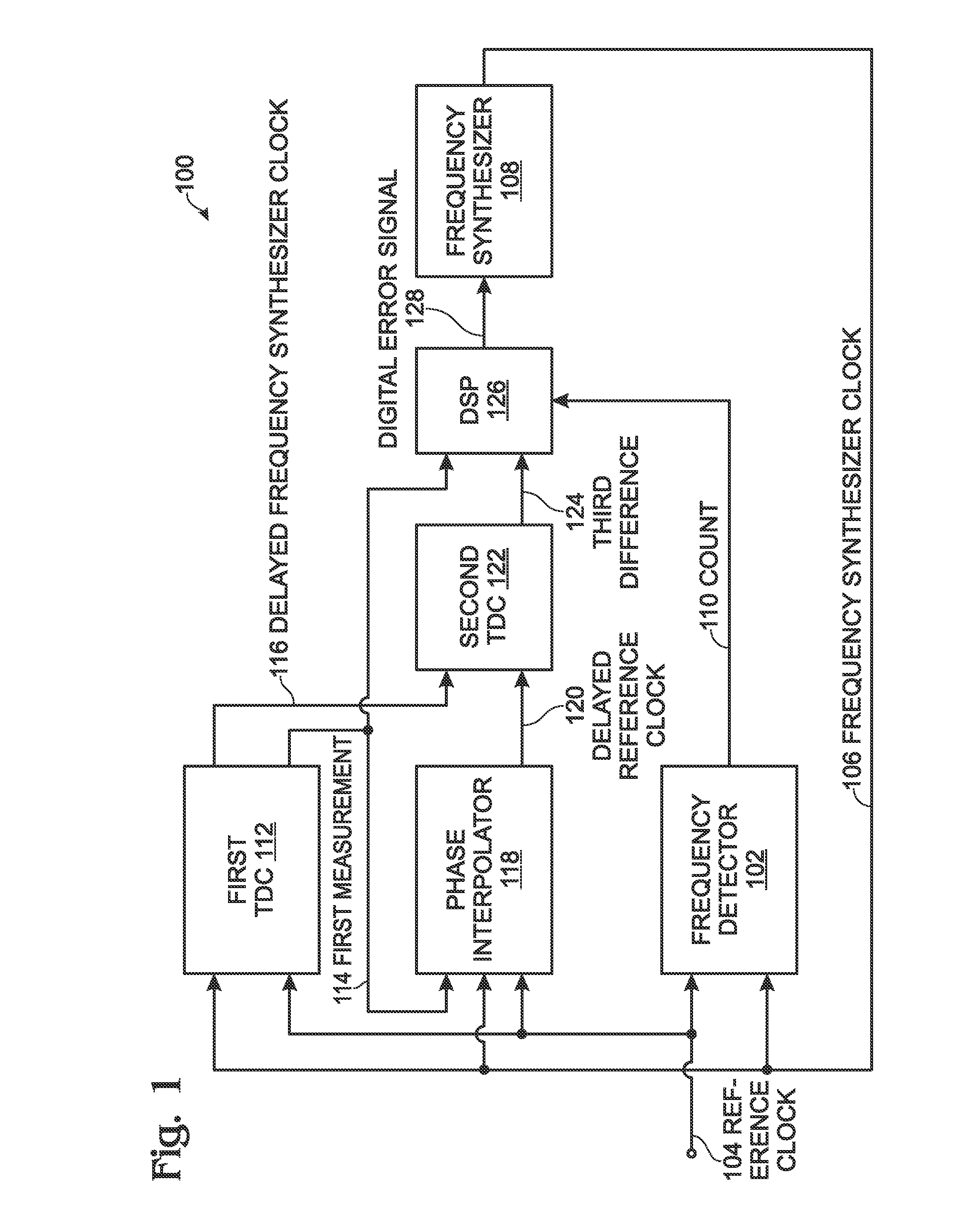
[0026]FIG. 1 is a schematic block diagram of a successive time-to-digital converter (STDC) and frequency synthesizer. The STDC 100 comprises a frequency detector 102 having an input on line 104 to accept a reference clock (REFCLK), and an input on line 106 to accept a frequency synthesizer clock (VCOCLK) from a frequency synthesizer 108. The frequency detector 102 has an output on line 110 to supply a count of the number of frequency synthesizer clock cycles per reference clock cycle (HSCNTROUT), also referred to as the count. A first TDC 112 has an input on line 104 to accept the reference clock, and an input on line 106 to accept the frequency synthesizer clock. The first TDC 112 measures a first difference between an edge of a reference clock period and a corresponding edge of a frequency synthesizer clock period, and provides the first difference measurement (CTDCOUT) at an output on line 114. The first TDC 112 also provides the frequency synthesizer clock delayed a full cycle (...


PUM


Abstract

A digital phase-locked loop (DPLL), a supporting digital frequency integrator, and a method are provided for deriving a digital phase error signal in a DPLL. A digital frequency integrator periodically accepts a digital tdcOUT message from a Time-to-Digital Converter (TDC) representing a measured ratio of a reference clock (Tref) period to a synthesizer clock (Tdco) period. Also accepted is a digital message selecting a first ratio (Nf). In response, a digital phase error (pherr) message is periodically supplied that is proportional to an error in phase between the reference clock and the (synthesizer clock*Nf).

Description

RELATED APPLICATIONS[0001]This application is a Continuation-in-Part of a patent application entitled, SUCCESSIVE TIME-TO-DIGITAL CONVERTER FOR A DIGITAL PHASE-LOCKED LOOP, invented by Hanan Cohen et al, Ser. No. 12 / 841,131, filed Jul. 21, 2010 now U.S. Pat. No. 8,106,808, which is incorporated herein by reference.BACKGROUND OF THE INVENTION[0002]1. Field of the Invention[0003]This invention generally relates to digital communications and, more particularly, to a system and method for generating a digital phase error message for phase-locked loop (PLL) applications.[0004]2. Description of the Related Art[0005]Digital PLLs (DPLLs) are an area of active research and development. A DPLL performs the loop filtering function in the digital domain with synthesized logic. DPLLs provide several advantages over the analog PLLs, including easier and faster implementation, and better controllability of the PLL parameters. Also, the integrated circuit (IC) die area devoted to the circuitry and ...

Claims


Application Information

Patent Timeline
IPC IPC(8): H03M1/48
CPCH03L7/081H03L7/093H03L2207/50
Inventor COHEN, HANANPANG, SIMON
Owner MACOM CONNECTIVITY SOLUTIONS LLC
Why Eureka
Try Eureka