
Method of compensating for a measuring error and an electronic arrangement to this end

a technology of measuring error and electronic arrangement, which is applied in the field of compensating for measuring errors, can solve the problems of reducing the ability of the cavity of the gas cell or sensor affecting the ability of one or more light receivers to receive and evaluate emitted, reflected and received light rays, and affecting the ability of one or more light receivers to reflect light rays

Inactive Publication Date: 2006-08-03
MARTIN HANS EVALD GORAN
View PDF0 Cites 55 Cited by
  • Summary
  • Abstract
  • Description
  • Claims
  • Application Information

AI Technical Summary

Benefits of technology

"The present invention relates to a method and electronic circuitry for compensating for measurement errors in gas sensors. The method is particularly useful for compensating for measurement errors that occur during long-term use or durability of the gas sensor. The invention is based on the recognition that measurement errors can be caused by changes in the environment or the ingoing components of the gas sensor. The invention uses an IR-sensor and signal processing circuitry to evaluate the light intensity with regard to wavelengths related to pulsated light rays emitted by a light source and received by a light receiver. The invention can be used in various gas sensor arrangements, such as those based on IR-technology or semiconductor sensors. The invention provides a way to compensate for measurement errors that are dependent on the time-wise slow change of ingoing components within the electronic circuitry and gas cell."

Problems solved by technology

With regard to Category “a”, Systematic errors these errors may also be related to the pressure, temperature, humidity prevailing ambient on the measuring occasion and also to other physical conditions prevailing around the gas cell or sensor and then particularly to the environmental circumstances around the gas cell sensor and its cavity, including mechanical influences brought about during transportation and the installation phase.
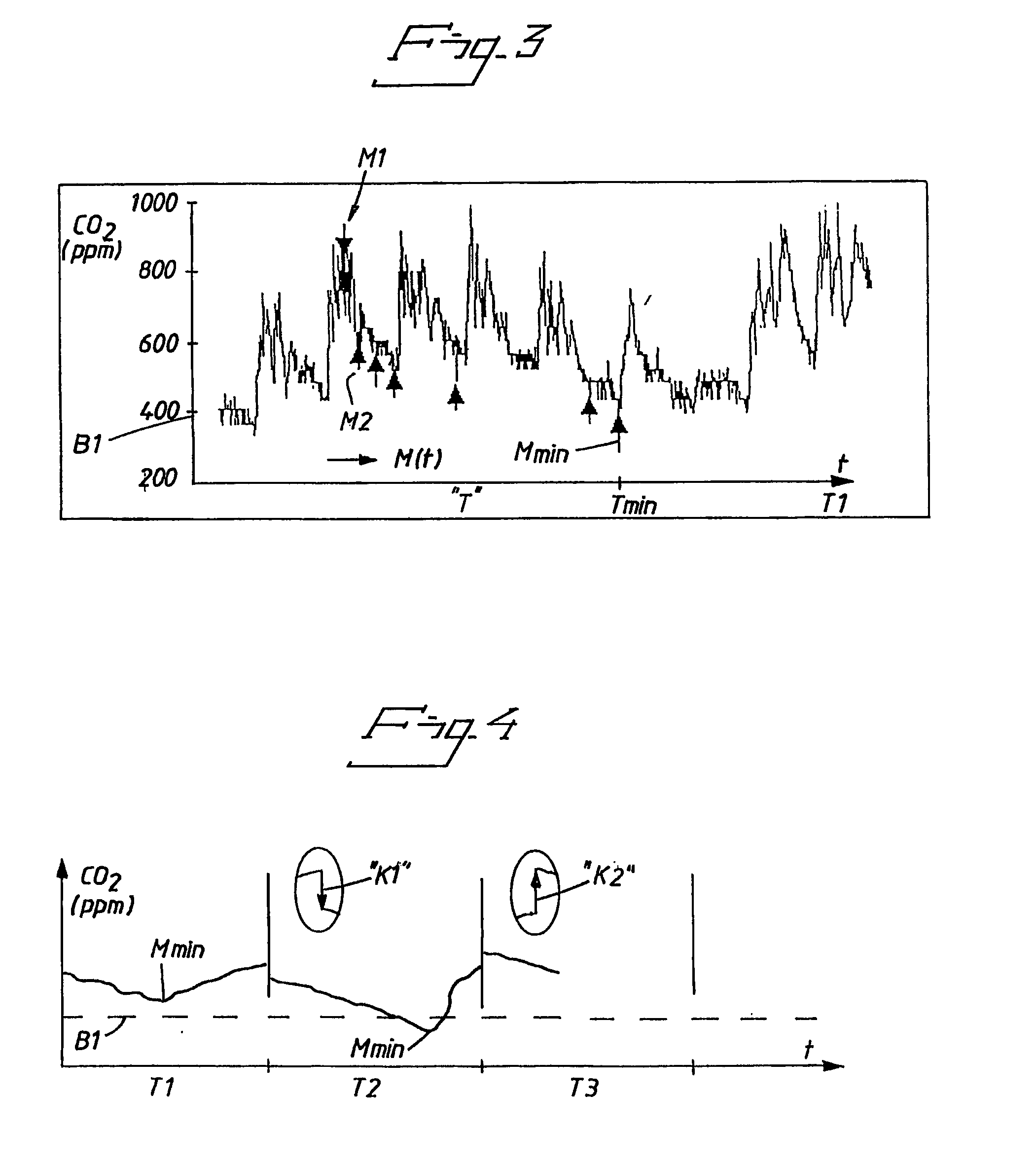
When using IR-sensors, the Category “c” error source also includes, among other things, the gradual reduction in the ability of the cavity in the gas cell or sensor to reflect light rays, an impaired change in the ability of the light source to send continuous light rays or pulsated light rays at a chosen intensity, an impaired change in the ability of one or more light receivers to receive and evaluate the emitted, reflected and received light rays, such as pulsated light rays.

Method used


Image

  • Method of compensating for a measuring error and an electronic arrangement to this end
  • Method of compensating for a measuring error and an electronic arrangement to this end
  • Method of compensating for a measuring error and an electronic arrangement to this end

Examples


Embodiment Construction

[0139] It is pointed out initially that we have chosen to use in the following description of embodiments at present preferred and including significant characteristic features of the invention and illustrated in the figures of the accompanying drawings special terms and terminology with the intention of illustrating the inventive concept more clearly.

[0140] It will be noted, however, that the expressions chosen here shall not be seen as being limited solely to the chosen terms used in the description, but that each term chosen shall be interpreted as also including all technical equivalents that function in the same or at least essentially the same way so as to achieve the same or essentially the same intention and / or technical effect.

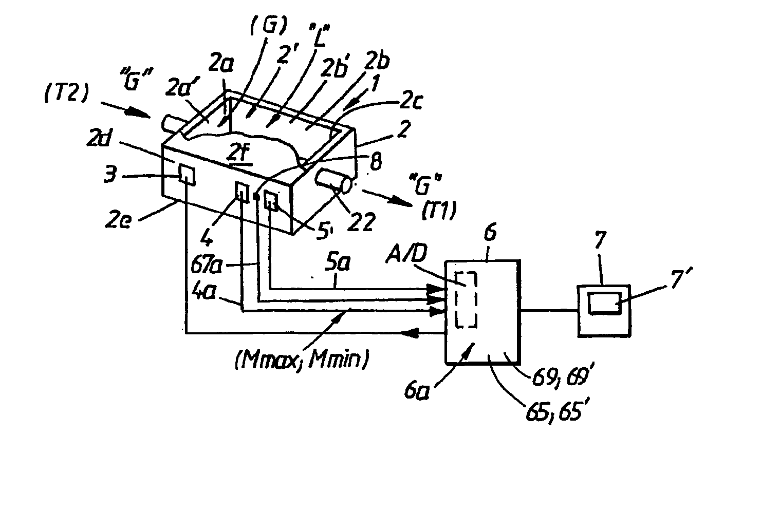
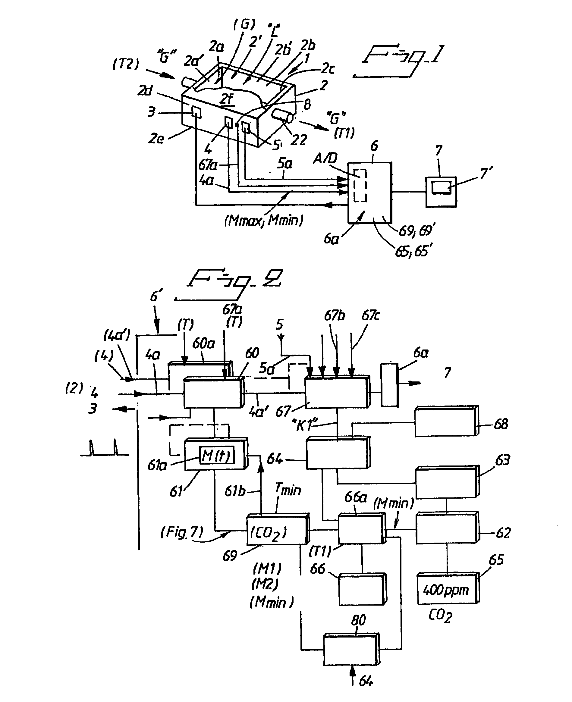
[0141]FIG. 1 illustrates diagrammatically the basic requisites of the present invention, wherein features significant of the present invention are generally concreted by virtue of proposed embodiments described in more detail hereinafter, one with r...


PUM

PropertyMeasurementUnit
temperaturesaaaaaaaaaa
timeaaaaaaaaaa

Abstract

A method and electronic arrangement for measuring errors with the aid of a gas sensor wherein a plurality of measurement valves occurring instantly during mutual sequential measuring cycles are detected. The electronic circuit arrangement has a plurality of circuit arrangements for compensating measurement errors wherein the measurements are affect with a gas sensor.

Description

FIELD OF INVENTION [0001] The present invention relates generally to a method of compensating for a measurement error that occurs in an obtained measuring value or result, and then particularly to a compensation of such measurement errors as those that occur subsequent to a chosen calibration of a measuring equipment and that can be considered to be related directly to such small changes that occur during a time-wise long use or duration. [0002] Measuring errors obtained when measuring the concentration of gases have been divided into the following categories, for reasons of a practical nature: a. Systematic errors. b. Errors of short duration. c. Errors related to time-wise long use or duration and successive errors. d. Pressure dependent errors. [0003] In this regard, it is known that a Category “c” measurement error is dependent on measurement errors associated with Categories “a”, “b” and “d”, and that efforts to compensate for Category “c” measurement errors will preferably...

Claims


Application Information

Patent Timeline
Patent Type & Authority Applications(United States)
IPC IPC(8): G01N31/00G01D3/036G01N21/27G01N21/35G01N33/00G01N37/00G06F
CPCG01D3/036G01D3/0365G01N21/274G01N21/3504G01N33/0006G01N2201/1211H04L27/00G01N21/27
Inventor MARTIN, HANS EVALD GORAN
Owner MARTIN HANS EVALD GORAN
Learn More