Structural analysis method employing finite element method

a structural analysis and finite element technology, applied in the direction of cad techniques, stress/warp reduction of printed circuits, instruments, etc., can solve the problems of huge data count, prediction accuracy drop, prediction computation takes time, etc., to shorten the structural analysis time and reduce the prediction accuracy

Inactive Publication Date: 2006-08-03
FUJITSU LTD
View PDF4 Cites 24 Cited by
  • Summary
  • Abstract
  • Description
  • Claims
  • Application Information

AI Technical Summary

Benefits of technology

[0008] Accordingly, the object of the present invention is to provide a structural analysis method, structural analysis p

Problems solved by technology

As a result, the data count is enormous and the prediction computation takes time.
Conversely, w

Method used


Image

  • Structural analysis method employing finite element method
  • Structural analysis method employing finite element method
  • Structural analysis method employing finite element method

Examples


Embodiment Construction

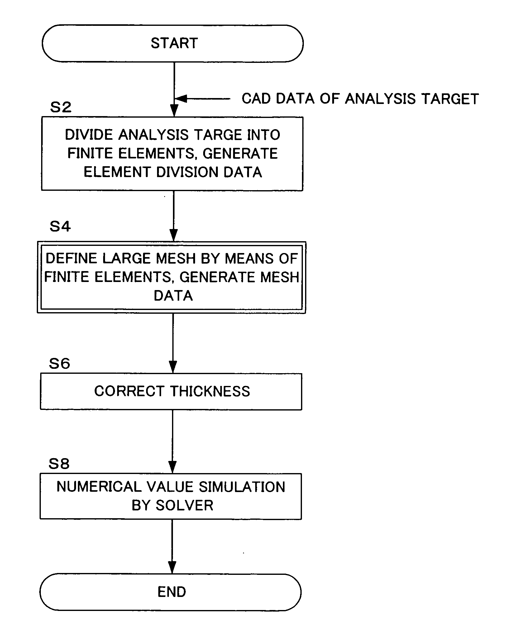
[0033] Embodiments of the present invention will be described below with reference to the drawings. However, the technological scope of the present invention is not limited to this embodiment but, rather, covers the inventions appearing in the claims and any equivalents thereof.

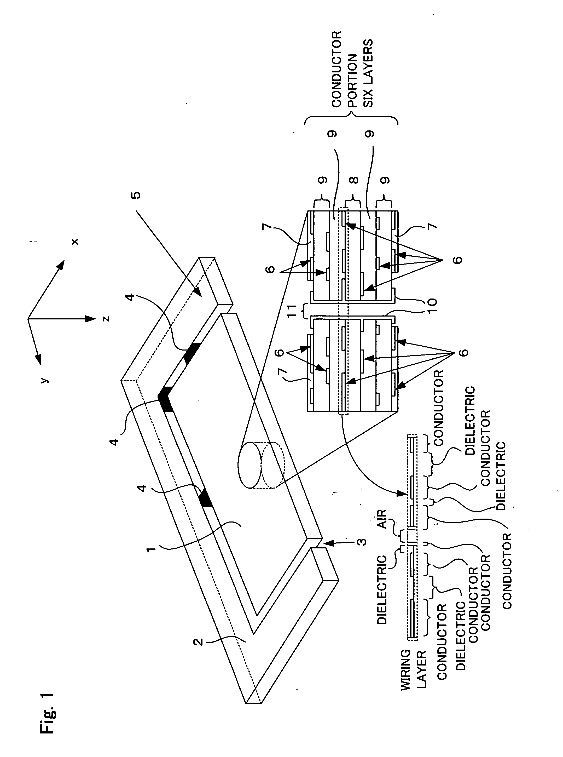
[0034] According to the embodiment of the present invention, a printed wiring substrate is used as the analysis target. Therefore, a print wiring substrate that is used in this embodiment is first simply touched on.

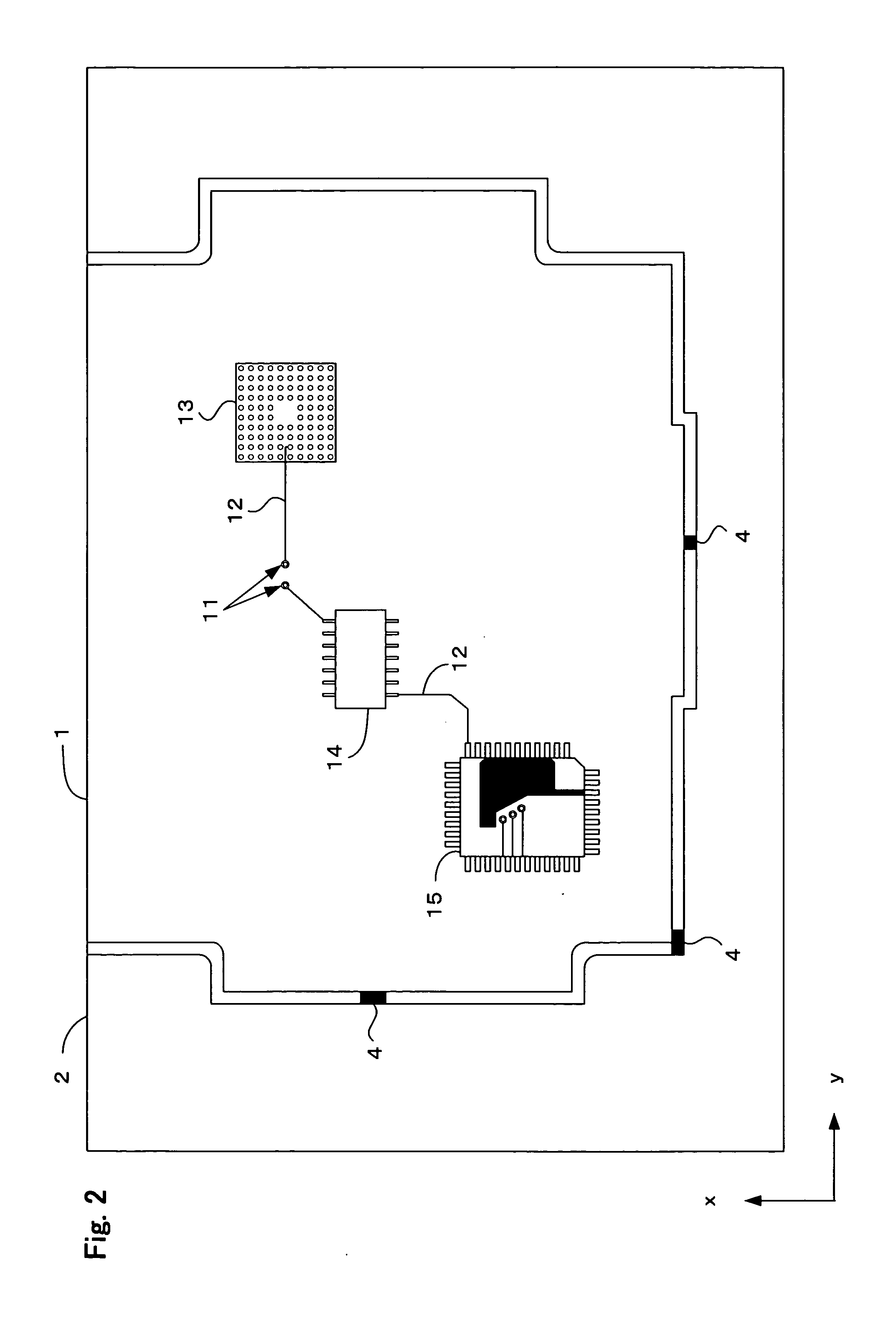
[0035]FIG. 1 illustrates the printed wiring substrate that is used in the embodiment of the present invention. The perimeter of the printed wiring substrate 1 is enclosed by a cut length 2. The printed wiring substrate 1 and cut length 2 are connected by ribs 4 and a groove 3 is formed at a point where no ribs 4 exist. The printed wiring substrate 1 and cut length 2 are separated by cutting the ribs 4.

[0036] The printed wiring substrate 1, rib 4, and cut length 2 are respectively composed of a m...


PUM


Abstract

A structural analysis method that saves analysis time without lowering the prediction accuracy is provided. The structural analysis method has dividing up the analysis target into a plurality of finite elements; defining a plurality of meshes that divide up the analysis target into units larger than the finite elements and calculating, for each mesh, the proportion of one material among the plurality of materials that occupy the finite element contained in the mesh; specifying a mesh in which the calculated proportion of the one material exceeds a predetermined threshold value and generating mesh data by substituting material information specifying materials other than the one material with material information of the materials of the finite elements contained in the specified mesh; and calculating the physical amount yielded in the analysis target on the basis of the generated mesh data.

Description

CROSS-REFERENCE TO RELATED APPLICATIONS [0001] This application is based upon and claims the benefit of priority from the prior Japanese Patent Application No. 2005-023463, filed on Jan. 31, 2005, the entire contents of which are incorporated herein by reference. BACKGROUND OF THE INVENTION [0002] 1. Field of the Invention [0003] The present invention relates to a structural analysis method employing the finite element method and, more particularly, to a structural analysis method to analyze a structural characteristic of a printed wiring substrate (strain characteristic, stress characteristic, thermal conduction characteristic, for example) by means of a numerical value simulation that employs a computer and refers to an associated program and structural analysis device. [0004] 2. Description of the Related Art [0005] A printed wiring substrate on which an integrated circuit pattern is formed by using the mask technology shown in Japanese Patent Application Laid Open No. H9-218032 ...

Claims


Application Information

Patent Timeline
IPC IPC(8): G06F17/10G06F17/50
CPCG06F17/5018G06F2217/16H05K1/0201H05K1/0271H05K1/0298H05K3/0005H05K3/4626H05K2203/162G06F30/23G06F2111/10
Inventor ITOH, NOBUTAKAKUBOTA, TETSUYUKINAKADATE, MAMITAMURA, AKIRA
Owner FUJITSU LTD
Why Eureka
Try Eureka