High milling resistance write pole fabrication method for perpendicular recording

Inactive Publication Date: 2006-08-10
WESTERN DIGITAL TECH INC
View PDF2 Cites 71 Cited by
  • Summary
  • Abstract
  • Description
  • Claims
  • Application Information

AI Technical Summary

Benefits of technology

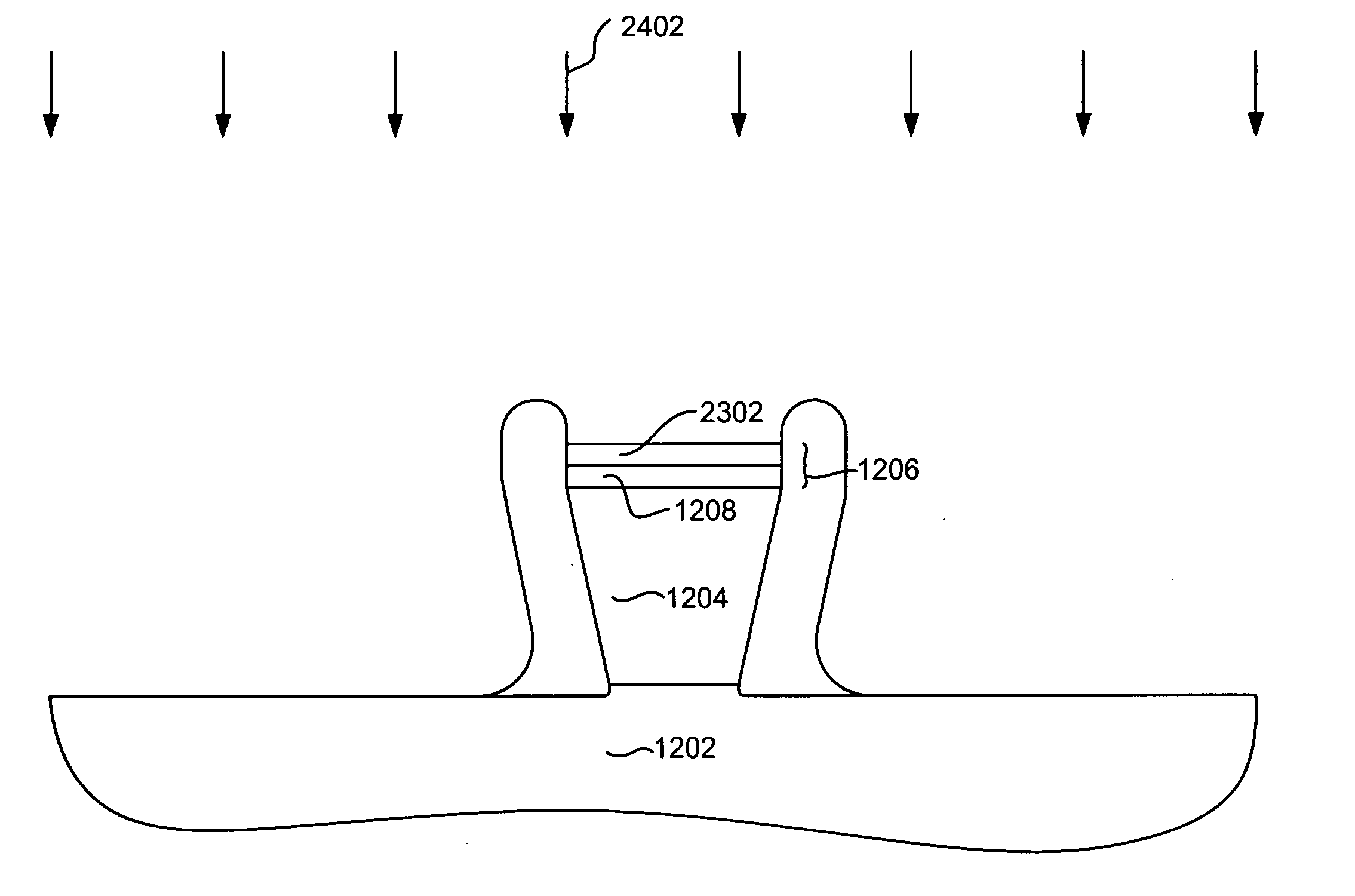
[0019] A method of manufacturing a magnetic write head using mask structures according to the present invention provides for the manufacture of a magnetic write pole having a very well defined shape

Problems solved by technology

Data density requirements are fast approaching the physical limits, however.
Because a large amount of flux is being forced into a relatively small write pole, when the write current is turned off the magnetization of the write pole does not immediately cease, but continues for an undesirably long period of time.
A problem that has been encountered with the above, however, is that due to poor RIE selectivity between the hard mask and the photoresist mask layer, the photoresist mask layer must be made very thick.
This is because a large amount of the photoresist must be consumed in the patterning of the hard mask.
As increased data densities require smaller track widths, the tall photoresist structure becomes problematic.
However, in general, thicker resist degrades resolution due to worsening aerial imaging in the case of deep UV lit

Method used


Image

  • High milling resistance write pole fabrication method for perpendicular recording
  • High milling resistance write pole fabrication method for perpendicular recording
  • High milling resistance write pole fabrication method for perpendicular recording

Examples


Embodiment Construction

[0031] The following description is the best embodiment presently contemplated for carrying out this invention. This description is made for the purpose of illustrating the general principles of this invention and is not meant to limit the inventive concepts claimed herein.

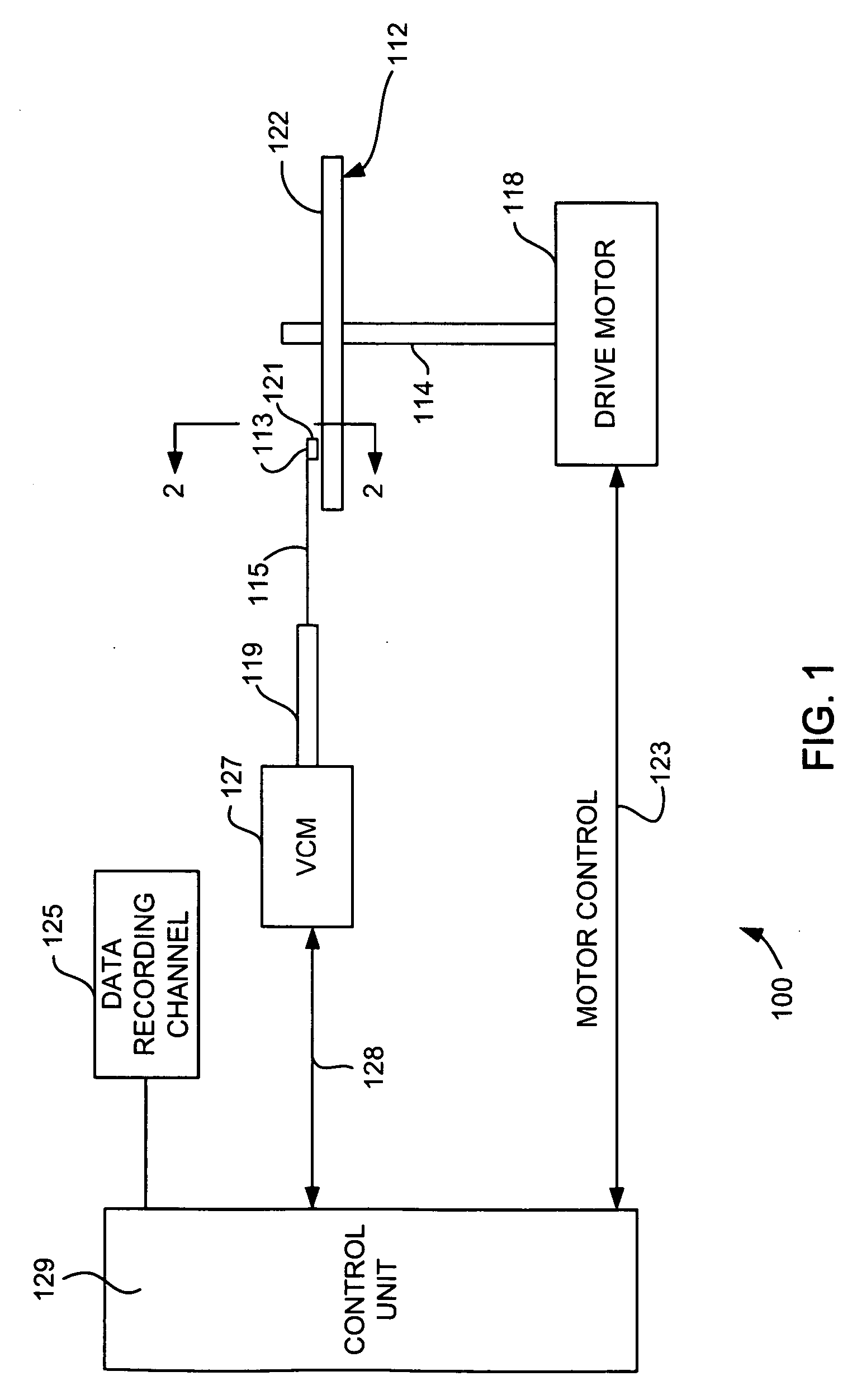
[0032] Referring now to FIG. 1, there is shown a disk drive 100 embodying this invention. As shown in FIG. 1, at least one rotatable magnetic disk 112 is supported on a spindle 114 and rotated by a disk drive motor 118. The magnetic recording on each disk is in the form of an annular pattern of concentric data tracks (not shown) on the magnetic disk 112.

[0033] At least one slider 113 is positioned near the magnetic disk 112, each slider 113 supporting one or more magnetic head assemblies 121. As the magnetic disk rotates, the slider 113 is moved radially in and out over the disk surface 122 so that the magnetic head assembly 121 may access different tracks of the magnetic disk where desired data are written. Eac...


PUM

PropertyMeasurementUnit
Wavelengthaaaaaaaaaa
Solubility (mass)aaaaaaaaaa
Wavelengthaaaaaaaaaa

Abstract

A mask structure for fabricating a write pole for a perpendicular write head. The mask structure includes a first and second hard mask structures separated by an image transfer layer, such as DURAMIDE®. The first mask structure may be a bi-layer mask structure that functions as a CMP stop as well as a hard mask for ion milling. The first hard mask is chosen to have a desired resistance to removal by ion milling to maintain excellent track width control during an ion milling process used to form the write pole. Therefore, the first hard mask may be comprises of two layers selected from the group consisting of Rh, alumina, and diamond like carbon (DLC). The second hard mask is constructed of a material that functions as a bottom antireflective coating as well as a hard mask.

Description

[0001] The present application is a Continuation in Part of U.S. patent application Ser. No. 10 / 836,867 filed Apr. 30, 2004 entitled HIGH MILLING RESISTANCE WRITE POLE FABRICATION METHOD FOR PERPENDICULAR RECORDING, which is incorporated herein by reference.FIELD OF THE INVENTION [0002] The present invention relates to perpendicular magnetic recording, and more particularly to a method for forming a tapered write pole for a perpendicular write head. BACKGROUND OF THE INVENTION [0003] At the heart of a computer is a magnetic disk drive that includes a magnetic disk, a slider where a magnetic head assembly including write and read heads is mounted, a suspension arm, and an actuator arm. When the magnetic disk rotates, air adjacent to the disk surface moves with it. This allows the slider to fly on an extremely thin cushion of air, generally referred to as an air bearing. When the slider flies on the air bearing, the actuator arm swings the suspension arm to place the magnetic head ass...

Claims


Application Information

Patent Timeline
IPC IPC(8): G11B5/127H04R31/00G11B5/187
CPCG11B5/1871Y10T29/49041Y10T29/49046Y10T29/49052Y10T29/49043Y10T29/49048G11B5/3116G11B5/3163
Inventor LE, QUANG
Owner WESTERN DIGITAL TECH INC
Why Eureka
Try Eureka