
Method of controlling the rate of oxygen produced by an oxygen concentrator

Active Publication Date: 2006-08-10
VBOX
View PDF49 Cites 44 Cited by
  • Summary
  • Abstract
  • Description
  • Claims
  • Application Information

AI Technical Summary

Problems solved by technology

Home oxygen concentrators, however, do have drawbacks.
They consume relatively large amounts of electricity; are relatively large and heavy; emit excessive heat and are relatively noisy.
Both of these options have significant drawbacks.
A major drawback of the cylinder option is that small cylinders only provide oxygen for a short duration.
Moreover, these cylinders are maintained at a high pressure, and thus their use is restricted due to safety considerations.
Another drawback of the cylinders is the refill requirement after depletion of the contents of the cylinder.
Filling of cylinders with oxygen in the home is potentially dangerous due to the physics involved with compressing gas.
Another detriment to cylinder usage is fire hazards associated with storage of large volumes of oxygen in the home environment.
Convenience and safety issues are not the only drawbacks associated with the use of cylinders.
Another drawback is the cost associated with cylinders.
Cylinders require special care, and specialized materials are required for high pressure oxygen compatibility, which in turn drives up the cost of cylinder-based systems.
The liquid oxygen storage system also has drawbacks.
The primary drawback is the requirement of a base reservoir which necessitates refilling once a week or more from an outside source.
However, there is substantial waste, as a certain amount of oxygen is lost during the transfer to the portable containers and from evaporation.
Up to twenty percent of the contents of the base cylinder is lost in the course of two weeks because of losses in transfers and normal evaporation.
When the patient is out in public, such stations are not readily available.
Such a requirement detracts from the ambulatory usefulness of the systems.
Thus, ambulatory equipment, or personal oxygen systems (POS), are to be inconspicuous to the public as well as unrestricting to the patient.
Cylinders and other liquid oxygen systems tend to be bulky, which interferes with normal daily activities.
Similarly, cylinders and liquid oxygen systems are difficult to conceal from public view.

Method used


Image

  • Method of controlling the rate of oxygen produced by an oxygen concentrator
  • Method of controlling the rate of oxygen produced by an oxygen concentrator
  • Method of controlling the rate of oxygen produced by an oxygen concentrator

Examples


Embodiment Construction

[0034] The current invention relates to separation of gases using vacuum swing adsorption. Specifically, disclosed is an oxygen concentrator for a patient who requires a source of oxygen. The present invention is further explained with reference to the drawn figures in which like structures are referred to by like numerals throughout the several views.

Overview—Oxygen Concentrator 100 (FIGS. 1-4)

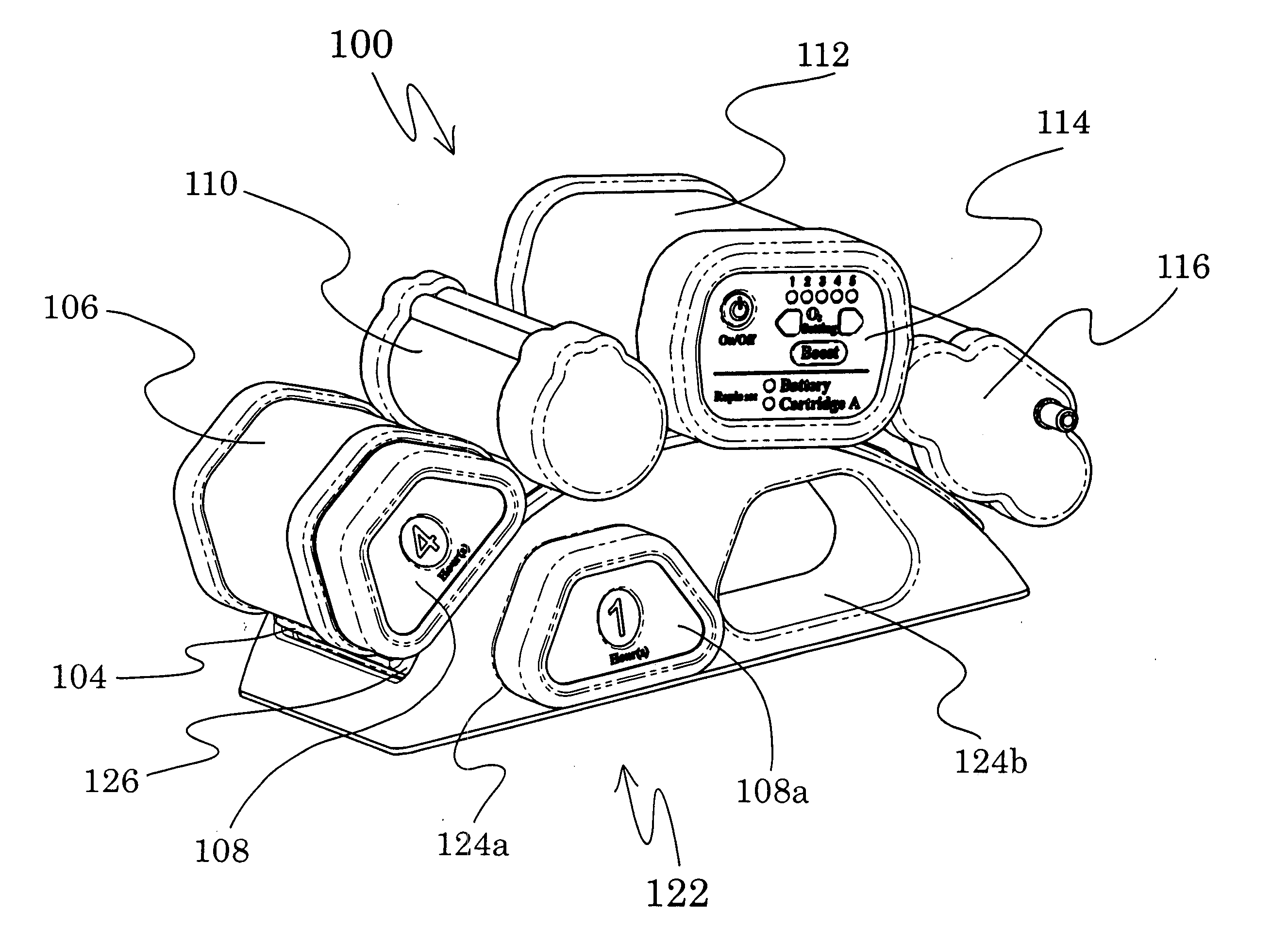
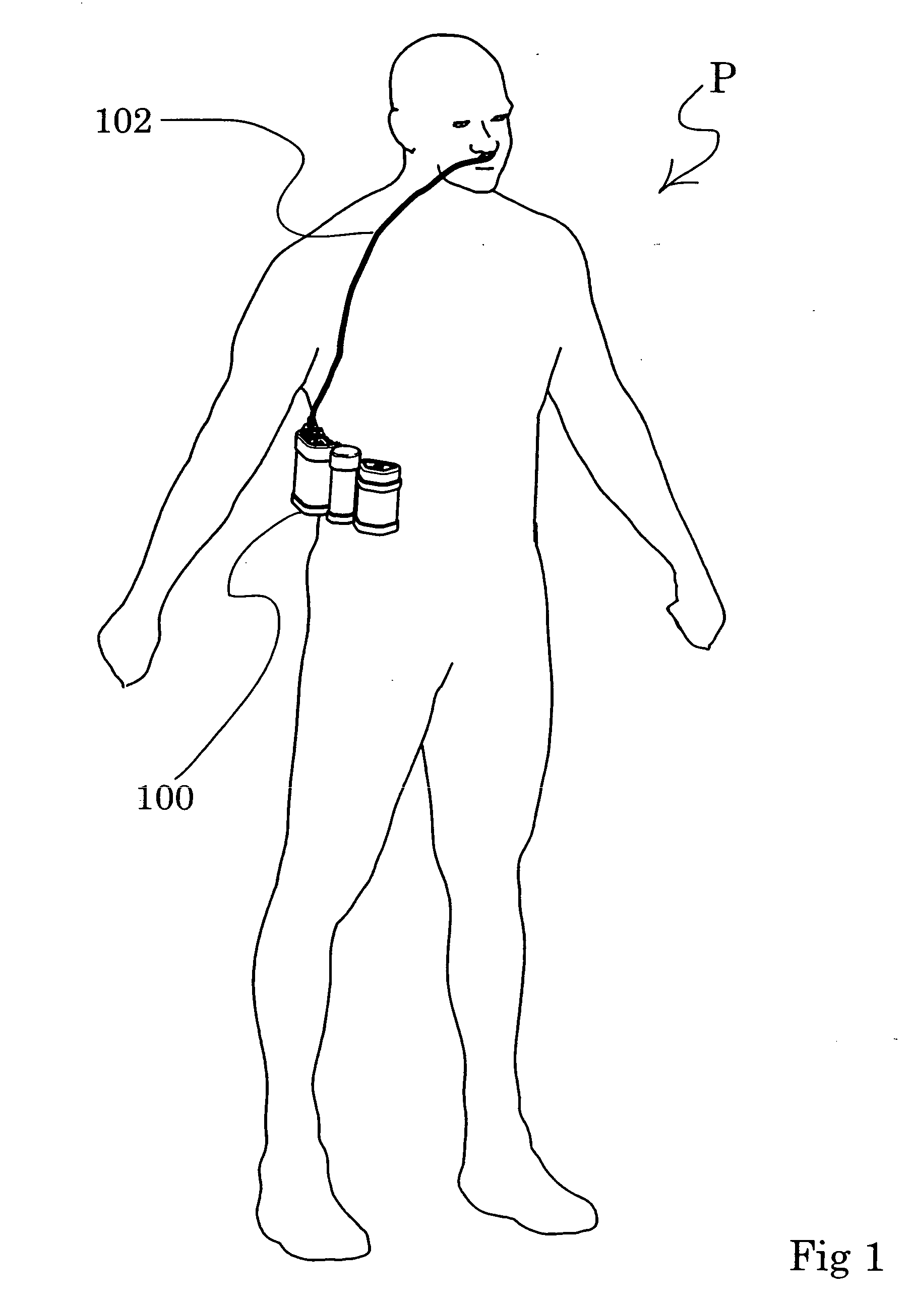
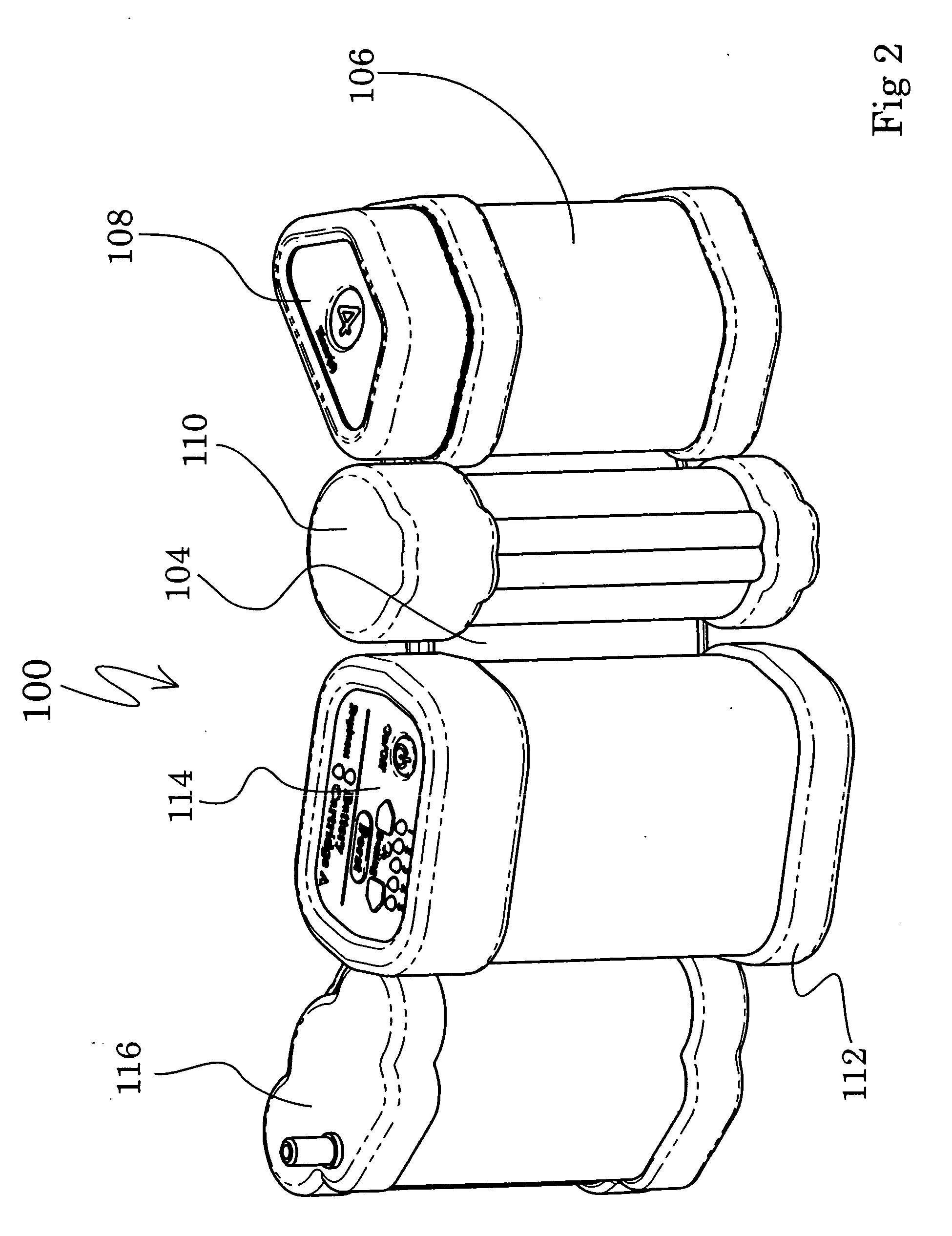
[0035]FIG. 1 is a front view showing patient P with oxygen concentrator 100 and oxygen delivery tube 102. Oxygen concentrator 100 is a small unit which utilizes vacuum swing adsorption to separate oxygen from the ambient air around patient P. Oxygen concentrator 100 is compact and light so as not to interfere with the ambulatory movement of patient P, and can produce a product stream of gas containing a range of eighty-five to ninety-five percent oxygen.

[0036] Oxygen delivery tube 102 is a polymer tube or similar oxidation resistant structure, which extends from oxygen concentrator 100 to...


PUM

PropertyMeasurementUnit
Pressureaaaaaaaaaa
Massaaaaaaaaaa
Massaaaaaaaaaa

Abstract

A method of providing concentrated oxygen product gas to a patient. The method comprises producing product gas by a vacuum swing adsorption (VSA) process with an oxygen concentrator comprising a plurality of separation columns connected to a vacuum source driven by a motor. Separated product gas is then pumped to a product reservoir. The pressure of the reservoir is monitored and used to adjust the speed of the motor based on the reservoir pressure. The separated gas is then delivered to the patient.

Description

CROSS-REFERENCE TO RELATED APPLICATION(S) [0001] Reference is hereby made to the following copending applications, which were filed on even date with the present application: “Ambulatory Oxygen Concentrator Containing a Power Pack”, Theodore W. Jagger et al., application Se. No. ______; “Adsorbent Cartridge for Oxygen Concentrator”, Theodore W. Jagger et al., application Ser. No. ______; “Ambulatory Oxygen Concentrator Containing a Three Phase Vacuum Separation Process”, Theodore W. Jagger et al., application Ser. No. ______; “Personal Oxygen Concentrator”, Theodore W. Jagger et al., application Ser. No. ______; “Method of Providing Ambulatory Oxygen”, Theodore W. Jagger et al., application Ser. No. ______; “Low Power Ambulatory Oxygen Concentrator”, Theodore W. Jagger et al., application Ser. No. ______; “Ambulatory Oxygen Concentrator With High Efficiency Adsorbent”, Theodore W. Jagger et al., application Ser. No. ______; “Portable Oxygen Concentrator With a Docking Station”, Theo...

Claims


Application Information

Patent Timeline
IPC IPC(8): A62B7/10A62B7/00
CPCA61M16/0666A61M16/10A61M16/101A61M16/107A61M2202/0208A61M2202/03A61M2202/0007
Inventor JAGGER, THEODORE W.VAN BRUNT, NICHOLAS P.KIVISTO, JOHN A.LONNES, PERRY B.
Owner VBOX
Learn More